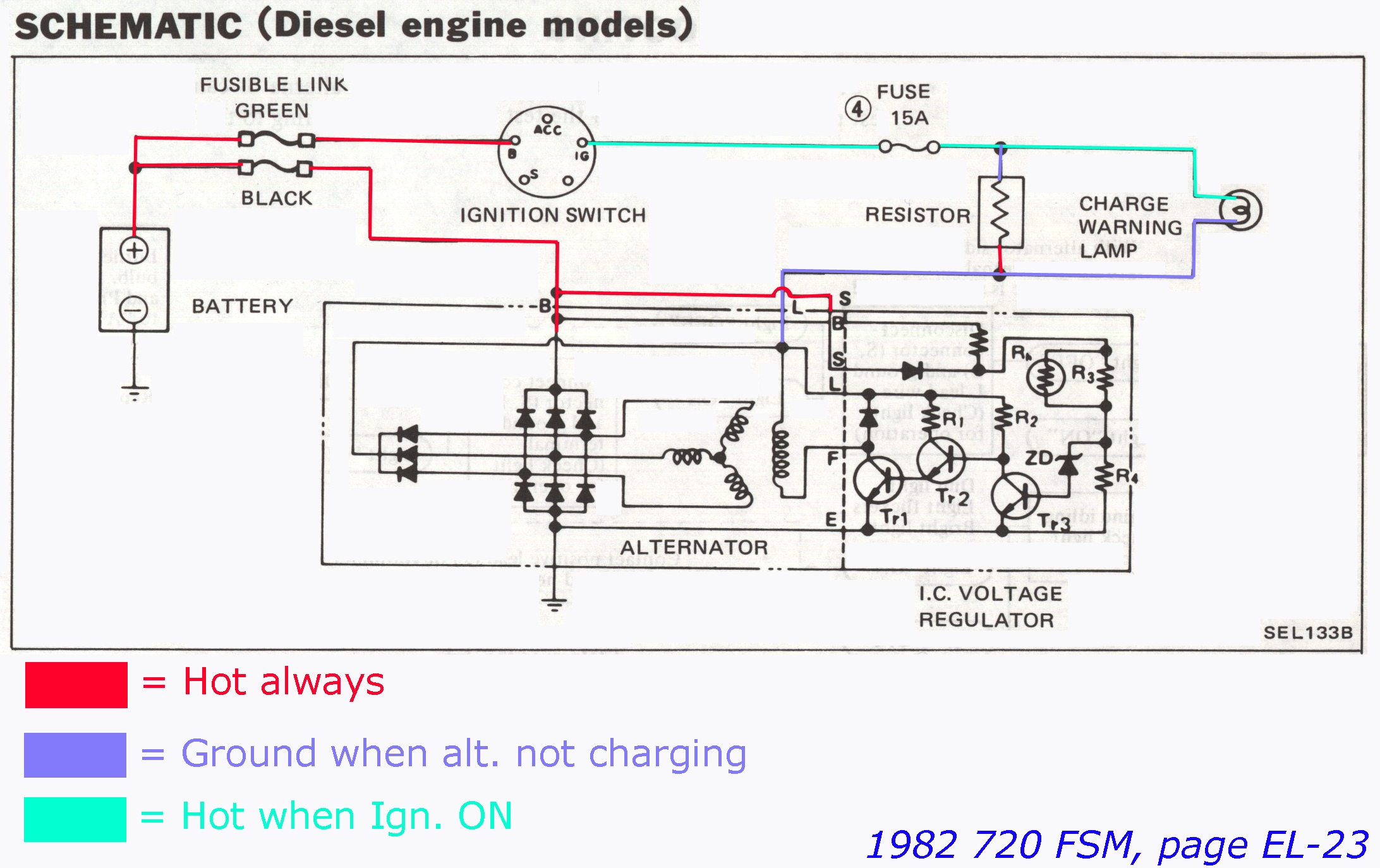
ecomike wrote:I find it curious that there is a 15 amp fuse listed in front of that resistor. Makes me wonder if 1 watt is anywhere near large enough for that resistor.
That schematic is a fragment, specific to the charging circuit. Fuse 4 feeds a lot more than just the charge idiot lamp.
While it
looks at first glance that the entire positive feed for the field coil (rotor) is via that fuse, the idiot lamp, and the resistor, that's only for startup, and you do not need much of a magnetic field to kick off an alternator. After startup, the alternator's diode trio (the three diodes to the left in the schematic, physically a lot smaller than the main diodes, because they don't have to do much) supply all the field coils' current. Which is why the idiot lamp goes out: 12v+ (nominal) on the Fuse 4 side of the lamp, 12v+ (nominal) on the "ground" side of the lamp: no current flow (or very little), no lamp light.
(Which is why some older rigs have a glowing idiot lamp when driving at night: with bad wiring, the alternator's voltage at the diode trio is higher than at the Ign. switch or fusebox.)
For that parallel resistor, 1W should be plenty. I do wonder at the actual resistance value though.
Scott at the alternator shop told me that many newer vehicles have the resistor built into the light bulb itself.
Scott must know something I don't. The lamp
is a resistor, and the normal resistance of the lamp allows (on most of these older alternators) enough current to kick off the alternator. GM & Ford didn't use a parallel resistor, and neither does the LR160 version of this alternator. I'd bet it's there to solve some intermittant, one-percent problem that most of us will never see. If the idiot lamp works, I bet the LR150 starts up just fine without the extra resistor.
New alternators are even wierder than that. Many VRs are now actually in the ECM, and it's now common for the VR to change charge value based on other conditions: when you step on the brake, the alternator bumps up to 15v, to do poor-man's regenerative braking (take advantage of wasted kinetic energy to accelerate the charge rate). Cold start: charge to lower value until the engine is idling smoothly and the load can be handled more gracefully (when the engine is warmed up). Like that. The modern VRs are now compensating for the phase variance internally (most alternators are three-phase).
But I wonder how yours is wired. I
suppose that having 12v+ to the
L terminal (without lamp or resistor) might work OK if you don't care about an idiot lamp and if the regulator doesn't fry, but it's going to mean pretty heavy current draw with key ON engine OFF (maybe two to five amps, which is relatively heavy compared to things like dome lights), and the wiring to the
L terminal is not designed to carry enough current to handle the capacity of Fuse 4. Summary: it
might be considered a fire hazard.
I'd use the lamp or a suitable replacement resistor. I doubt that the actual resistor value is all that important.
Makes me wonder if Nissan might not have already been doing that in 82.
No, I've seen what I think may be the resistor on the left fenderwell of a couple of early 720 diesels. I just haven't taken the time to confirm it.
I picked up a standard AC SCR dimmer/ceiling fan variable speed controller / switch today, 600 watt, that I plan to use for speed and power usage control of the AC condenser fan, it should help me drop the power load on the alternator some. Even though they are sold for AC, 120 volt devices, IIRC they also work on DC in DC out DC motor loads as I used one for DC battery charging research once.
I want to see you use an SCR with DC input to do phase-chopping output to 12v fans! I really do!
Save yourself some grief: get a big dropping resistor from any 80's Taurus at a JY, wire it in series with your fan(s), mount a switch near your dash, and wire the switch to bypass (short out) the big resistor. Efficient? No, you'll have heat dissipation to deal with, the resistor will be dropping 2-4 volts but a lot of current. But simple and reliable. Two fan speeds is enough.
If you run multiple fans, do away with that idea and have them come on in stages. You can either use dual thermostat triggers, or if you must get complex, use a thermister and a microcontroller to toggle individual relays for each fan.
The possibilities are plentiful. But SCRs like to switch at phase zero-crossing, and you don't have zero-crossing with DC. I'm not an EE though, I don't even play one at work.
I also bought an aftermarket bulb and capillary variable control thermal switch that I am going to use to cycle the AC condenser fan, as I probably only need it at idle, and for extended idling in heaving traffic.
I no longer have the schematic for the system I installed in my '83 G30, in 1994, but you will need to use an A/C high-side pressure switch (cheap, at any large A/C repair center) to toggle your fans to get idle fan control. That's what I did, it worked a charm. I had custom-engraved LED panel indicators (the lenses were engraved, very cool) made to tell me when the fans were on because of the A/C pressure switch, or if they were one because of thermostat demand. I added a third engraved indicator that read "A/C cycling switch" to let me know when the compressor was running too. I was pretty proud of that.