Thanks to Al for posting this EGR System wiring diagram.
How would one go about using the check connector for testing the system?
YR and YL should be -12V (actually ground?) when throttle butterfly is supposed to be closed and EGR valve energized, correct?
R should be +12V when RPM/load/temp call for IP advance, correct?
Check connector can be accessed via the square opening in the instrument panel lower cover, just inboard of the hood release handle. I realize the check connector could be giving correct readings while the signals may not be getting to the solenoids. Don't the wires (post check connector) run thru the troublesome bundle under the fuel filter?
EGR System Troubleshooting
Moderators: plenzen, glenlloyd, goglio704, Nissan_Ranger
-
asavage

- Site Admin
- Posts: 5435
- Joined: 18 years ago
- Location: Oak Harbor, Wash.
- Has thanked: 1 time
- Contact:
Re: EGR System Troubleshooting
(I've just put back a wire on that connector I'd removed, because I didn't think anyone would care about it: WB, 12v+ switched/fused.)

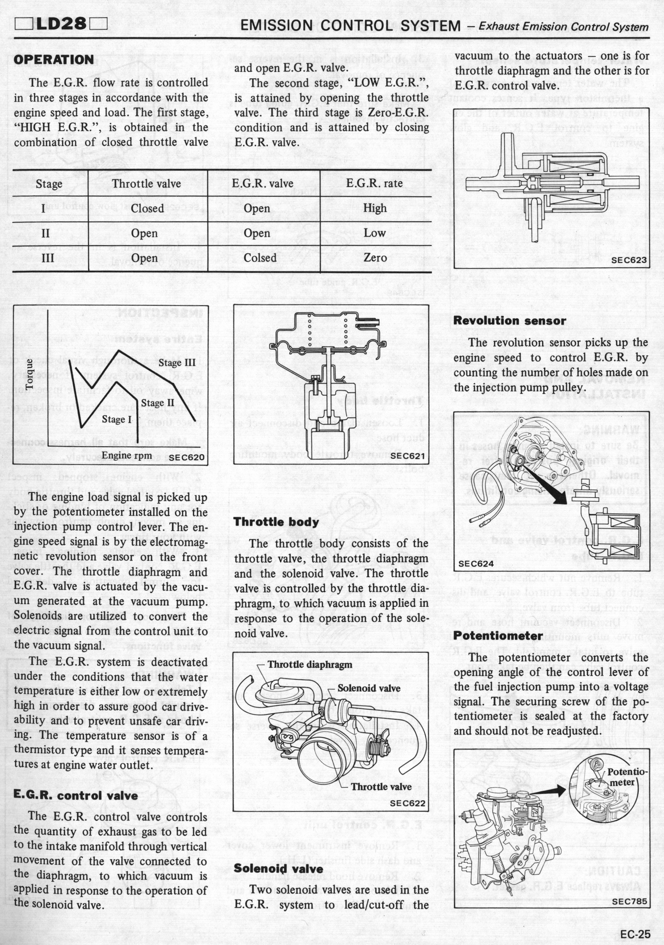
Yes. However, refer to the chart on 1982 FSM, page EC-25:Carimbo wrote:How would one go about using the check connector for testing the system?
YR and YL should be -12V (actually ground?) when throttle butterfly is supposed to be closed and EGR valve energized, correct?
(Remember: this applies to 1981 and '82 ONLY, because Nissan did something different in 1983 for EGR control.)
(click on image for larger)

There are times when only the EGR valve solenoid will be energized ("Stage II"), and other times when both the EGR valve solenoid and the throttle valve solenoid will be closed ("Stage I").
[Note the misspelling: "Colsed" in Stage III.]
You could wire a couple of low-wattage lamps or LEDs between
- The White/Black wire (which is switched 12v+) and R, to see when the IP Advance solenoid fires;
- The (Black [which is Ground] & YR) and (B & YL) wires, to see when those two solenoids fire.
Yes, in "Stage I" and "Stage II" operations.R should be +12V when RPM/load/temp call for IP advance, correct?

Possibly. It's not part of the main engine harness that runs on the passenger side of the engine (which contains the GP wires).I realize the check connector could be giving correct readings while the signals may not be getting to the solenoids. Don't the wires (post check connector) run thru the troublesome bundle under the fuel filter?
-
asavage
- Site Admin
- Posts: 5435
- Joined: 18 years ago
- Location: Oak Harbor, Wash.
- Has thanked: 1 time
- Contact:
Re: EGR System Troubleshooting
The EGR test connector does not use std terminals. I was going to build a test box with LEDs, but I have to come up with the male terminal elements.Carimbo wrote:How would one go about using the check connector for testing the system?
Who is online
Users browsing this forum: Ahrefs [Bot] and 2 guests