A 120/240v 1ph Onan genset came up for sale on CL (Seattle) in early June. I forwarded the ad to Dad (in South Pasadena, Calif.) and he asked me to check it out. It was in Issaquah, 120 miles east of me.
The situation turned out to be that the fellow was remodeling an already good-sized house (10k sq/ft), and the "little" Onan 20Kw genset was inadequate and old, so he purchased a made-in-China-by-Gawd 50Kw genset to replace/upgrade it. It was onsite in a crate and needed to go where the old Onan lived. The Onan ES was supposed to be a good running power plant.
The story is that Floyd (Seller) has had it for a number of years. Previous owner to Floyd had it installed in a service van of some sort. When the hours racked up, PO wanted a newer, less used rig.
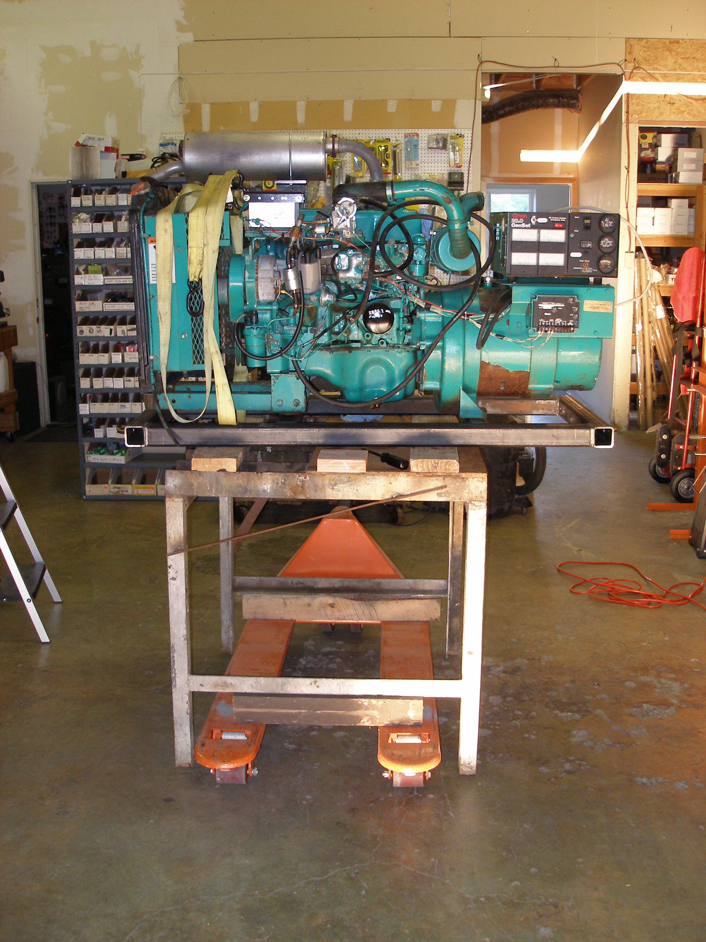
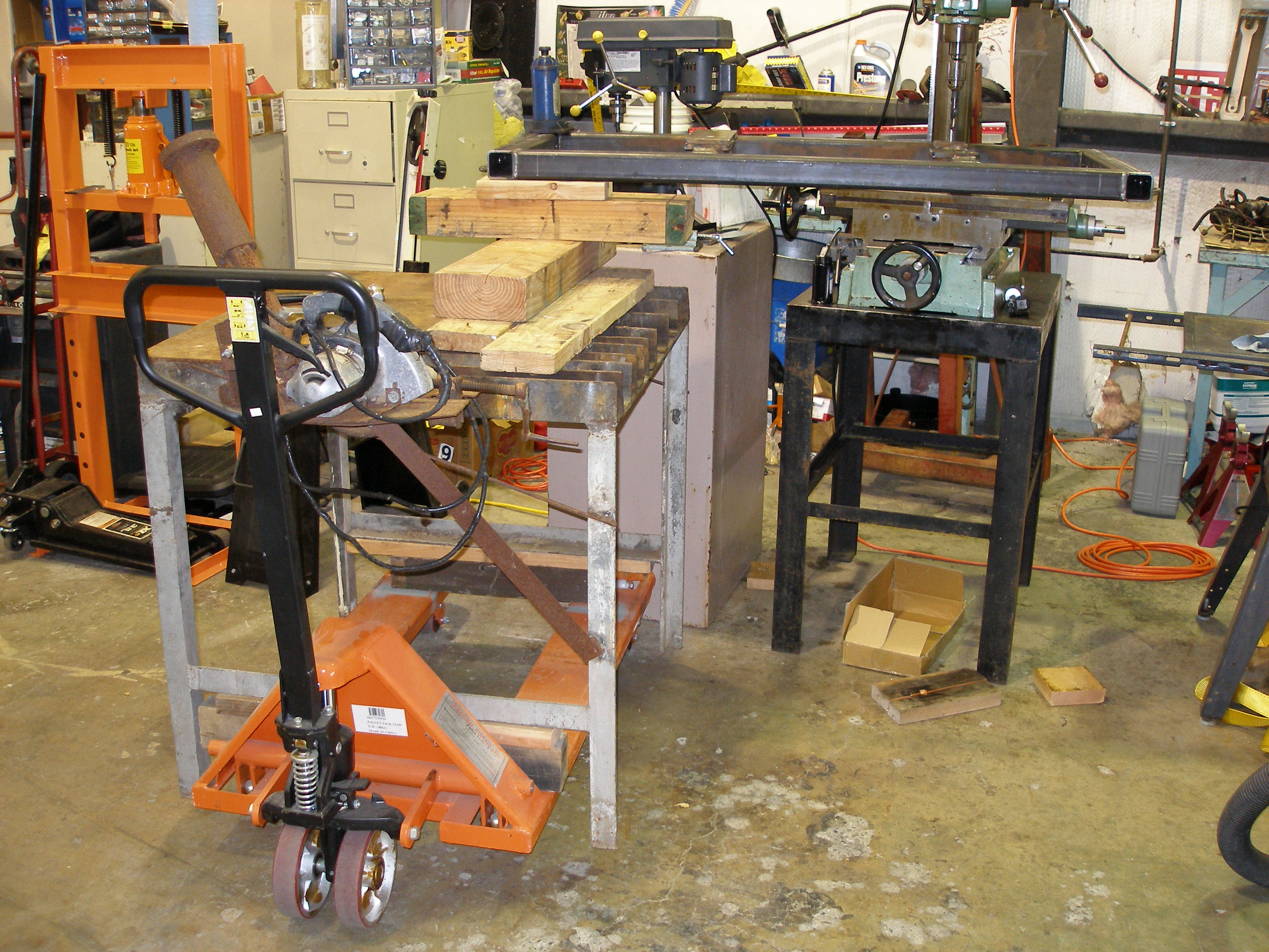
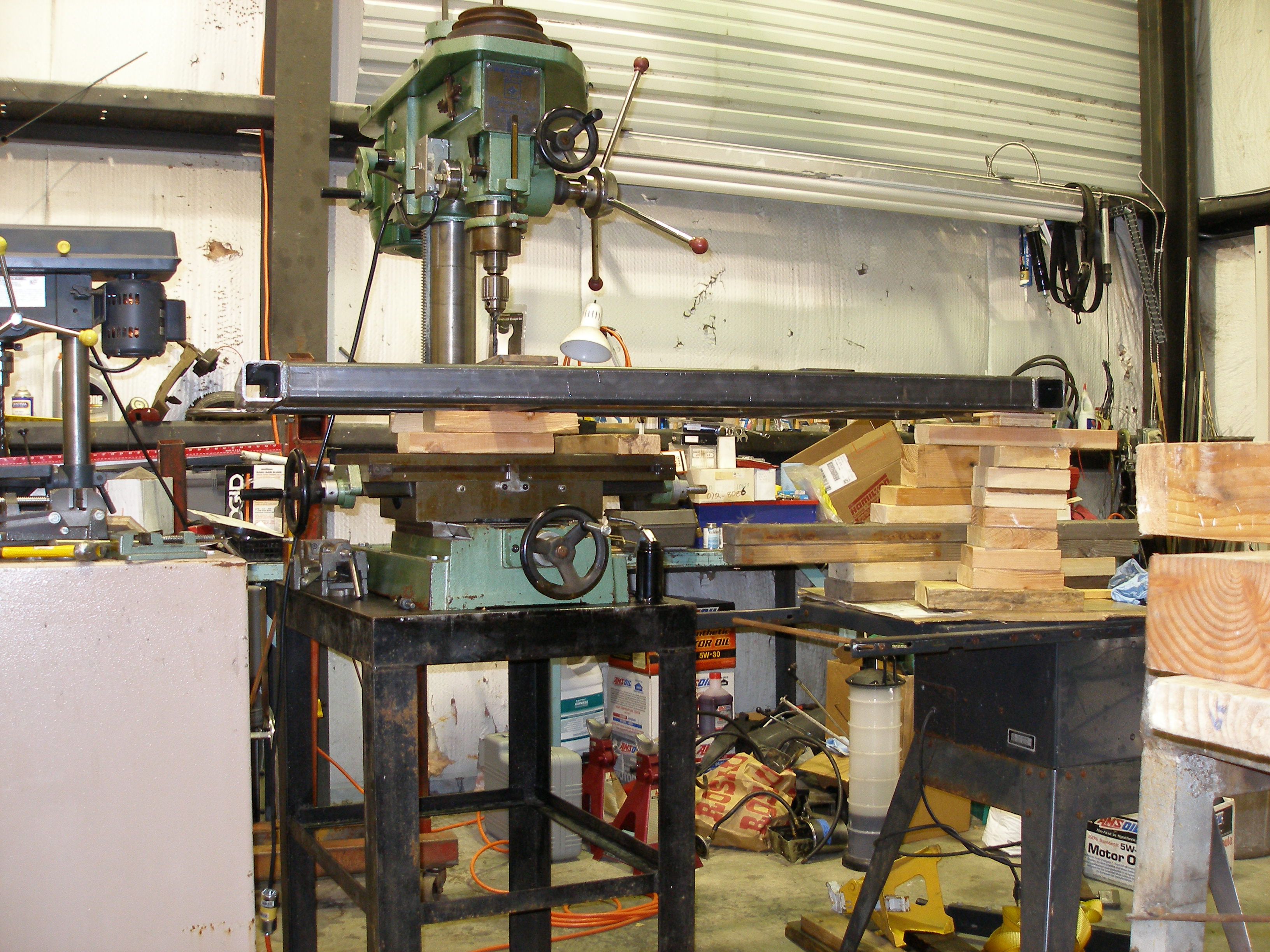
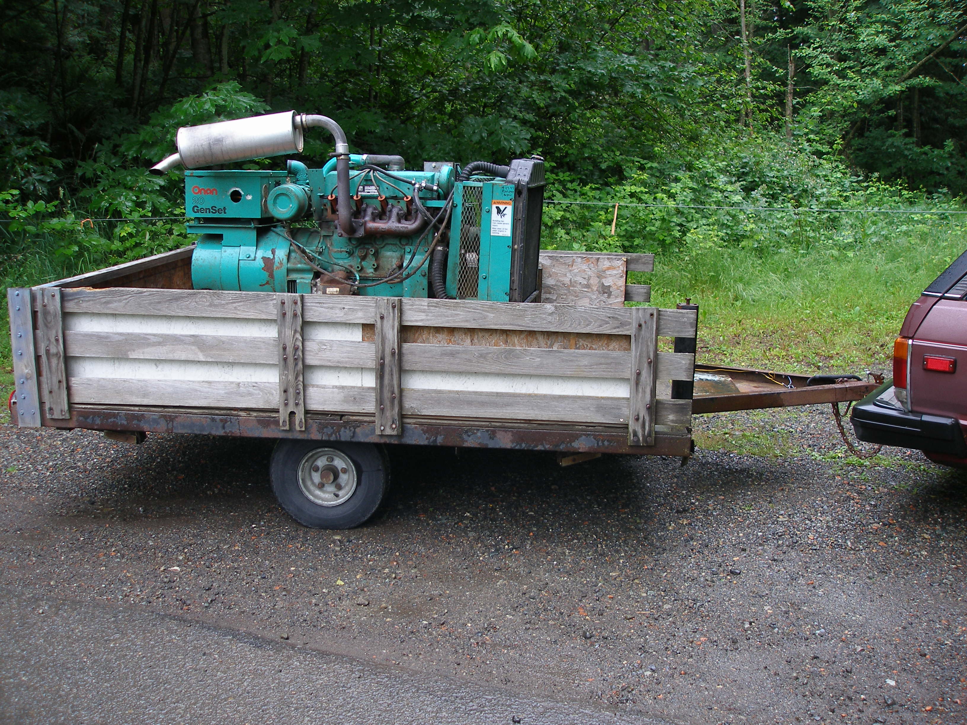
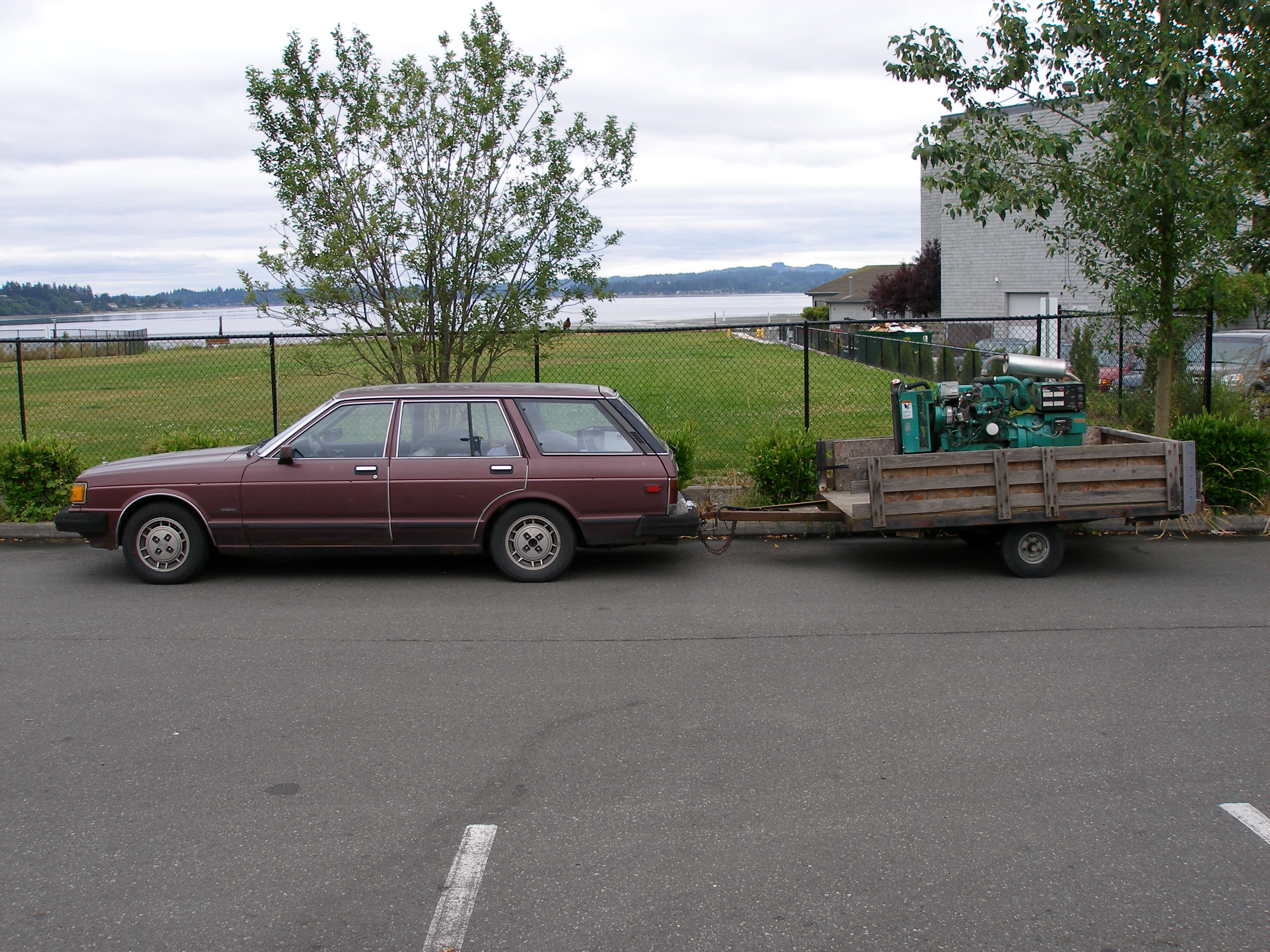
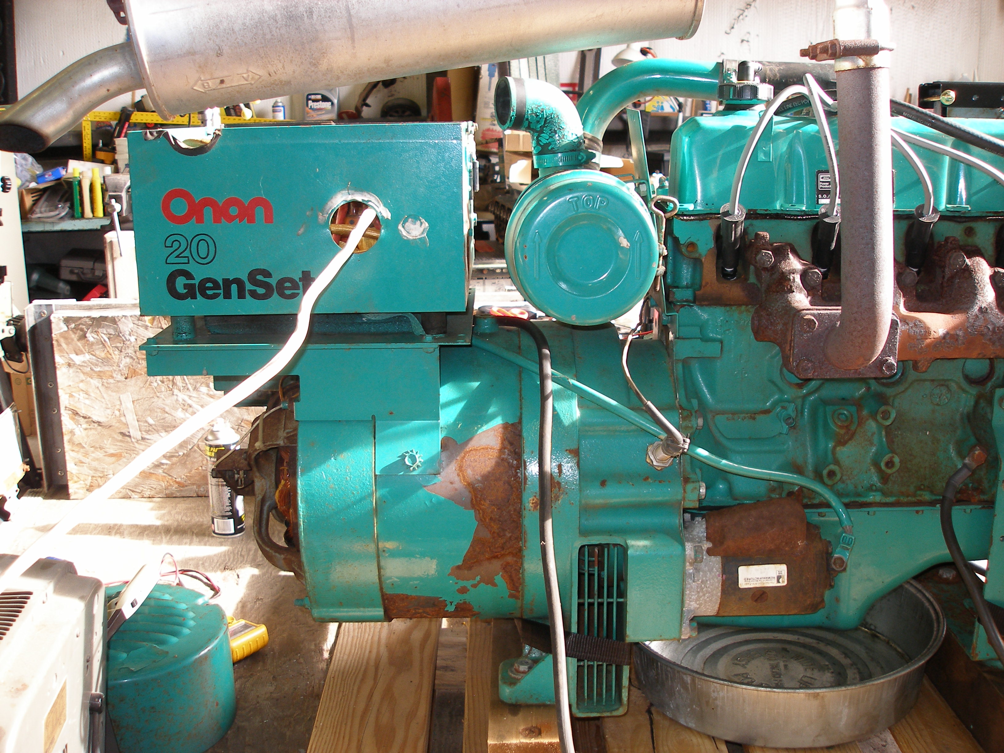
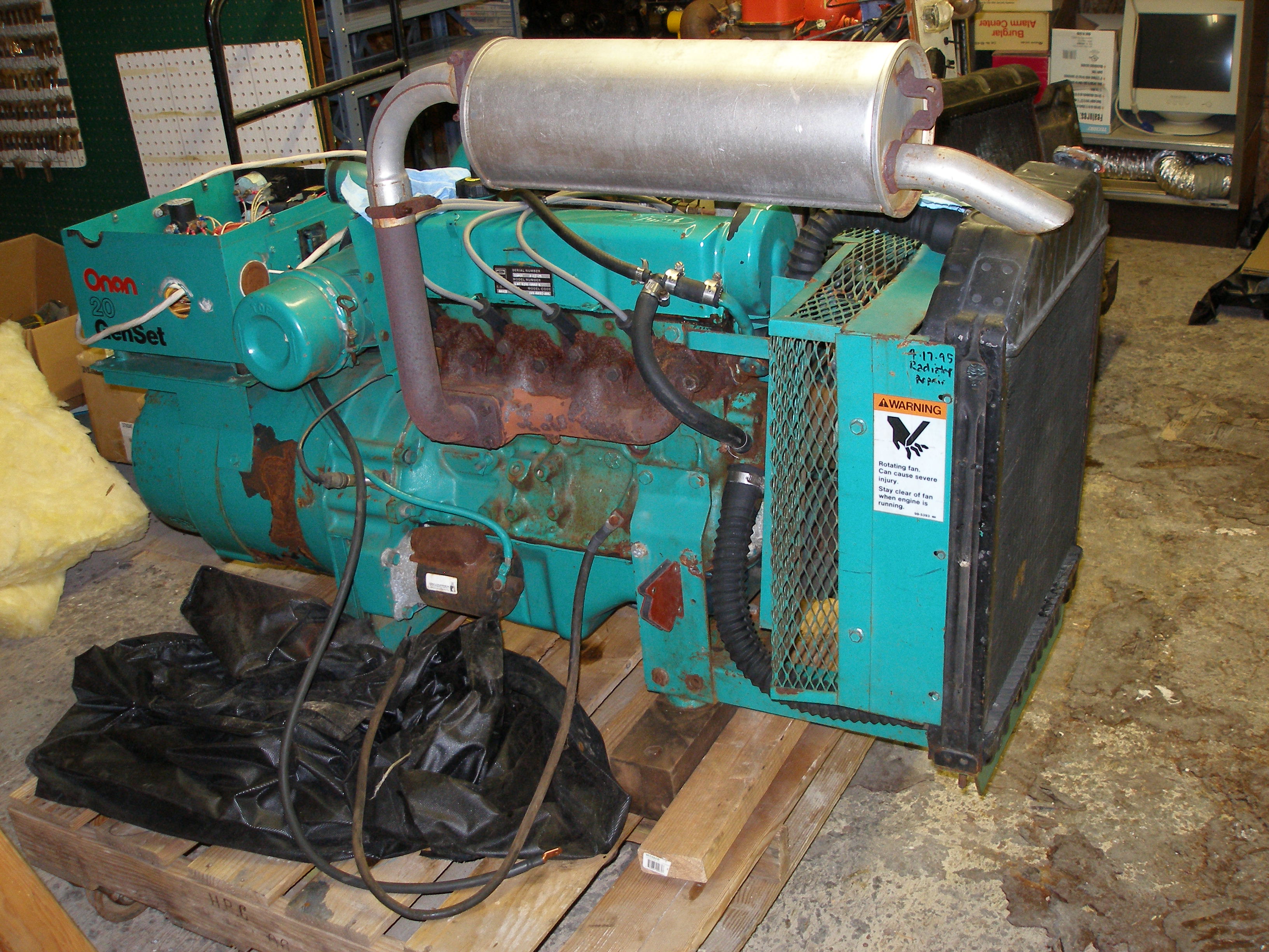
I arranged to meet Floyd on Saturday, 16-Jun and look-see this Onan. As I first saw it:
(click on any image for larger)

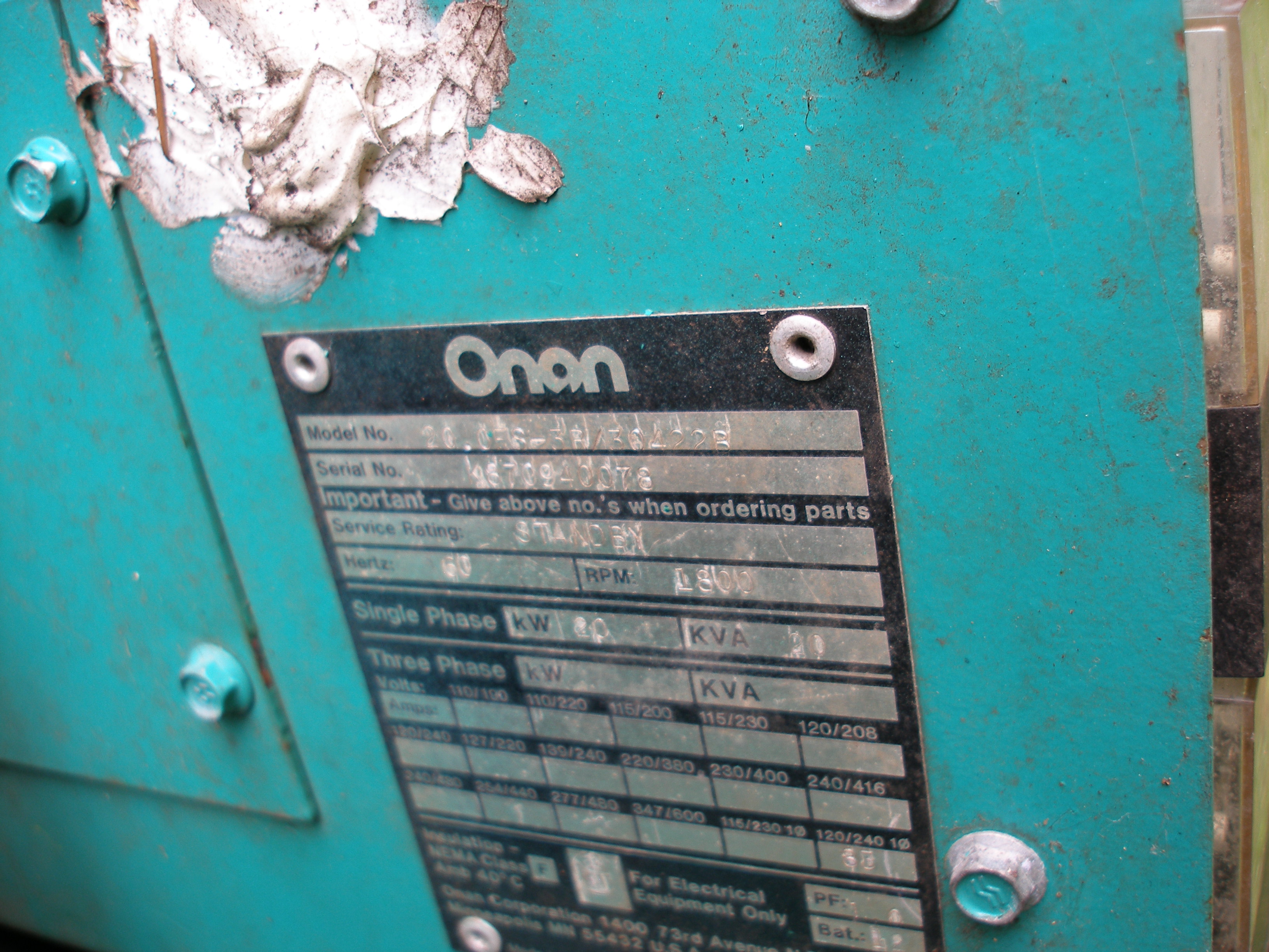
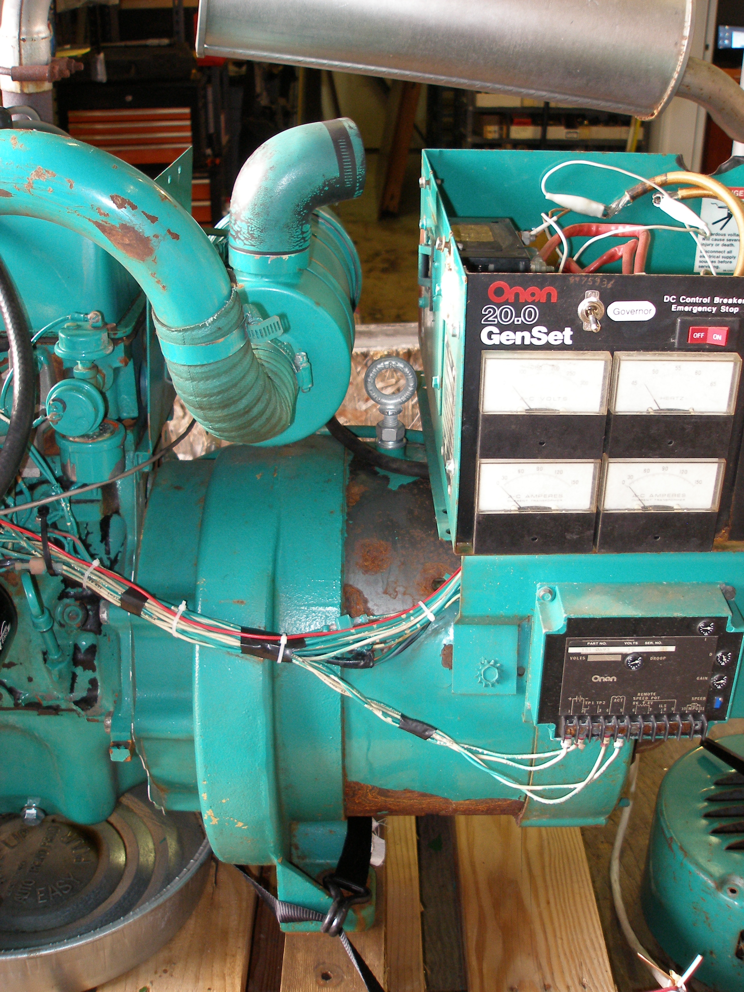
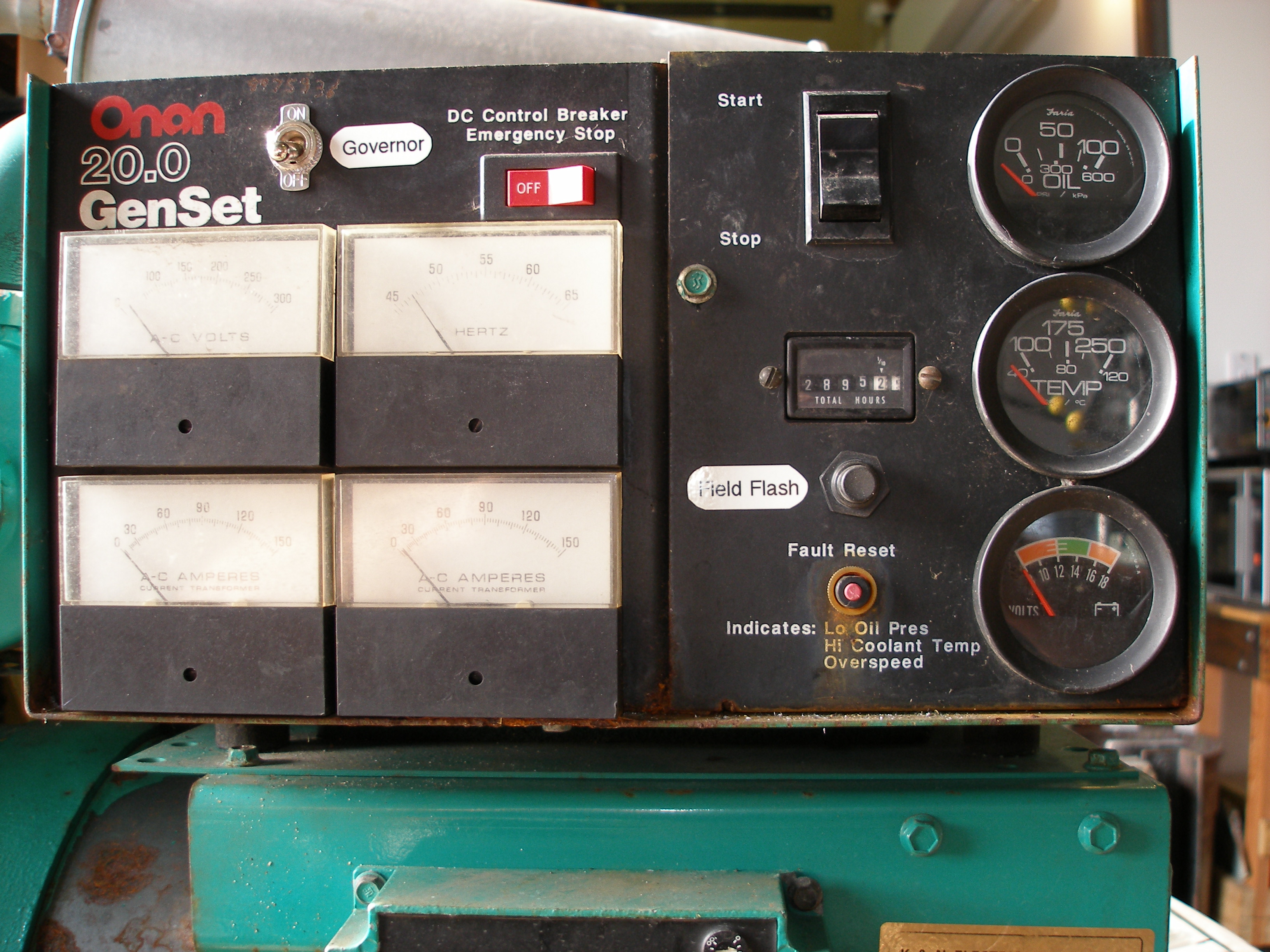
Genset
Model: 20.0 ES 3R/30422B (ie "Spec B")
Serial: K870940078 (ie Nov-1987)
Engine
Ford Industrial LSG-423I-6005-A (Pinto engine)
Special Options code 0032M
Model Code TCA-0032-JBA
Serial Number 22043 S-27-TH
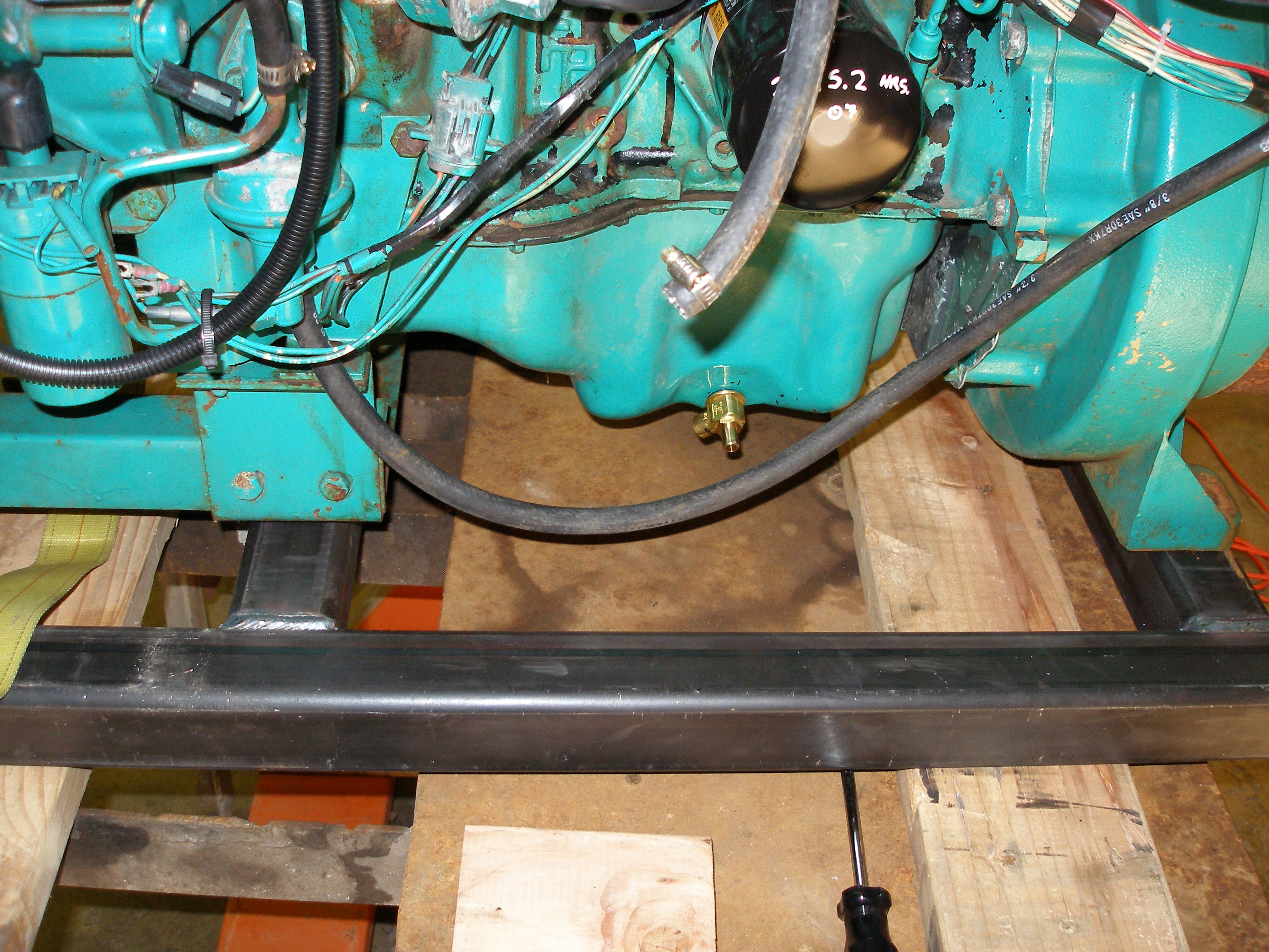
Hourmeter shows 2894 hours.
Floyd says he used it for more than one day only once in all the years he's had it. Other than that, it has been run for an hour here and an hour there. It has been tarped (has a semi-custom-fitted cover, but no enclosure). He ran it last week and load-tested it somewhat, then ran the ad.
He fired it up and it ran fairly well, a few burbles and misses but sounding basically healthy. Oil dirty but full, coolant OK, no drips or leaks and not recently cleaned of old grime so nothing hidden by that. We talked while it warmed up -- temp too low, I noted, so a bad thermostat in there.
It is approx. 6' long, 30" wide, with the two skids being 20" (the wood, that is) and the skids being 23" center-to-center.
It has a 2.3l Ford industrial engine (that looks like both the one I had in a '70s Bobcat, and a Pinto!). It runs very quietly.
The battery and steel gravity-feed fuel tank come along with it, as well as the fitted tarp arrangement.
After warmup, Floyd then threw the transfer switch. Nothing: no power coming from the genset. For a generator, this is bad.
I offer to come back when it's working, he thinks about his deadlines and logistics, says he doesn't want to fix it, he wants it gone. Asking price is $1800, which Dad has authorized if it looks like it's OK. I offer Floyd the pig-in-a-poke price of $1000 -- if he loads it in my trailer. He agrees, and we make a date for tomorrow: Sunday.
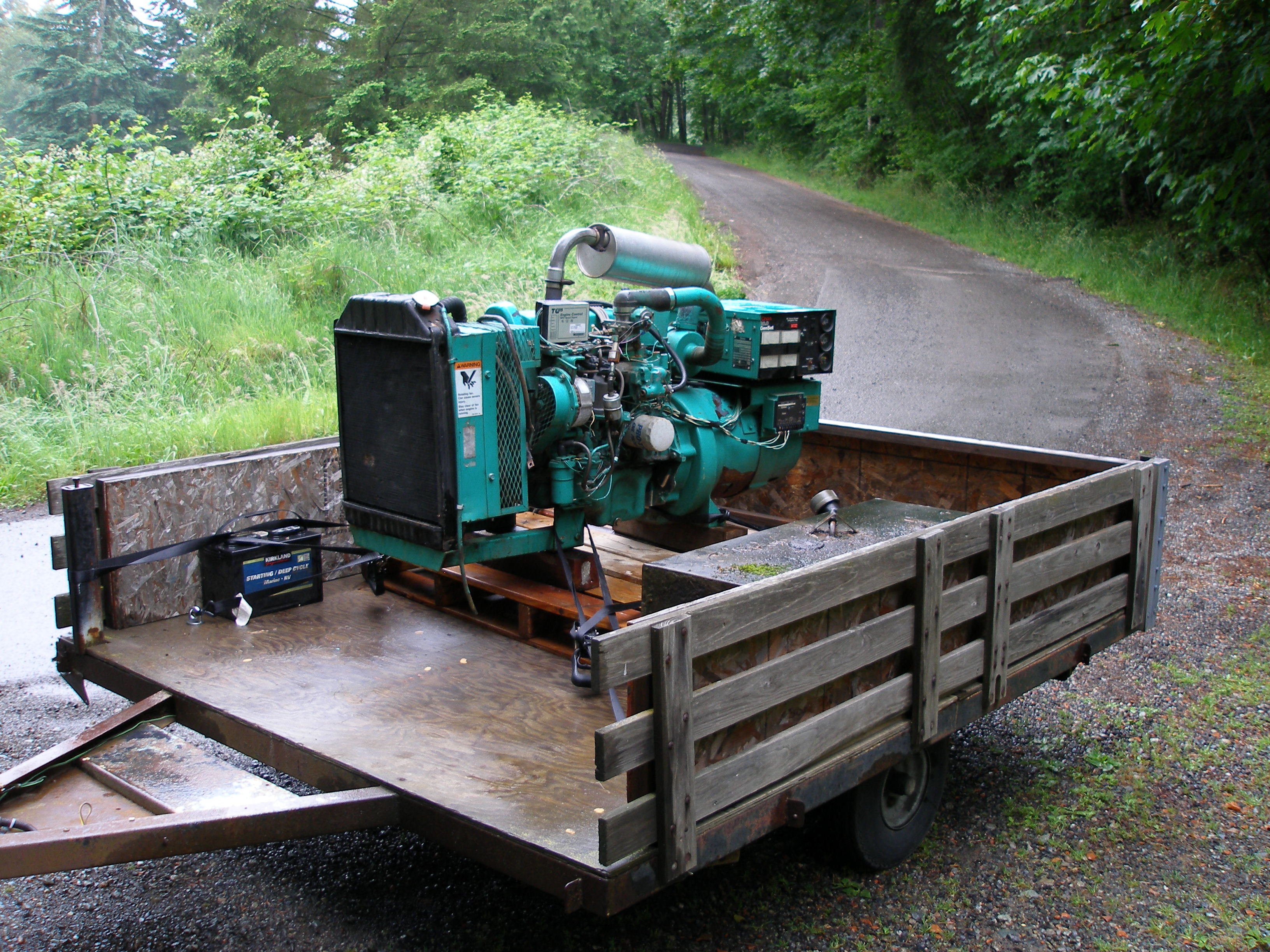
240 miles later, I show up noon Sunday with my '82 Wagon and the shop's 6'x7' utility trailer that has seen so much use by me by now that I should own it! I write a check in the misty rain, and Floyd maneuvers his fork-tines-on-loader-bucket arrangement under the now-palleted genset, and sets it on the trailer. The trailer squats as he lowers the load. A lot. I begin to feel the creepy tendrils of worry up my back. However, I've hauled 1800 lbs on this trailer in the past -- slowly, and behind my grey '89 Aero, which had 50 more HP and a lot more brakes than the '82 Wagon.

So I make my way -- carefully -- home another 120 miles, take it to the car wash and rinse away the small amount of grime and moss it's accumulated out in Issaquah over the years. It cleans up well, but some non-obvious rust appears.
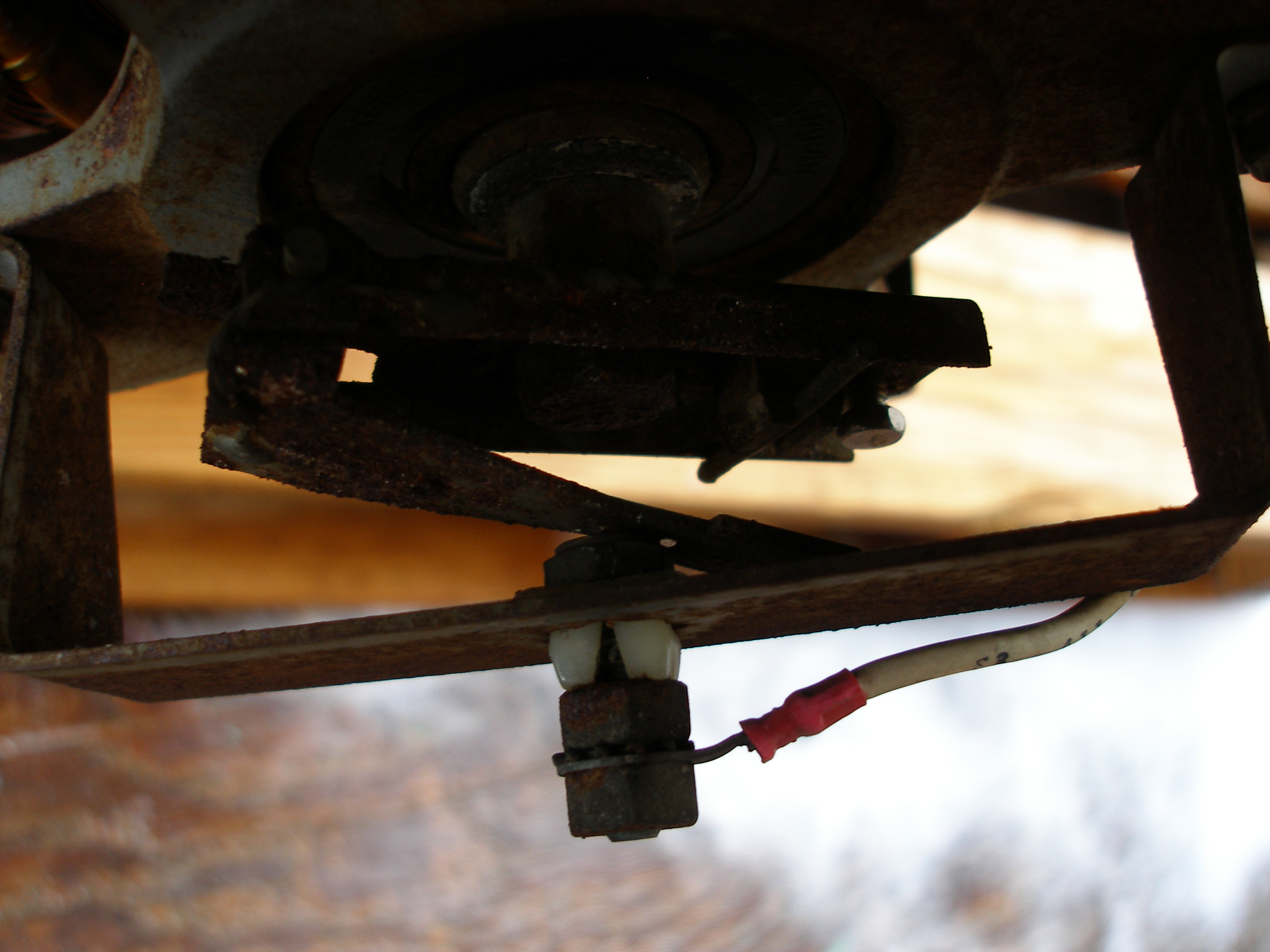
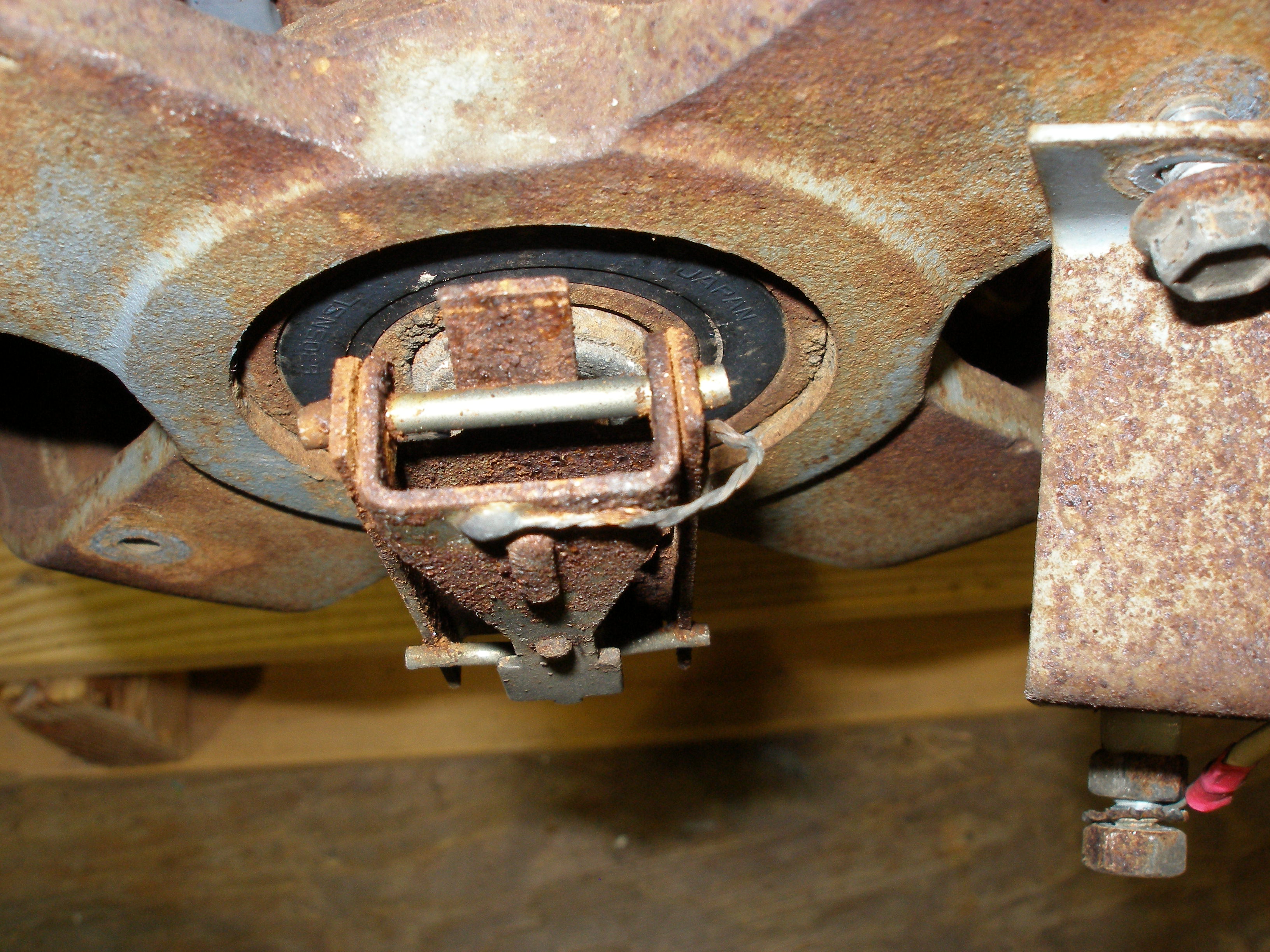
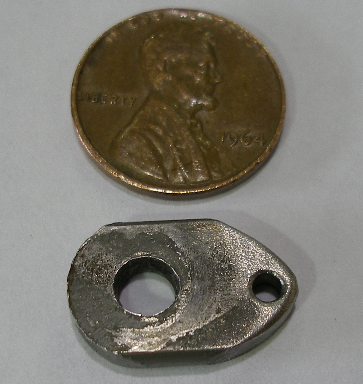
That last is the overspeed switch, "before" condition. I later cleaned it up so it actually does something.
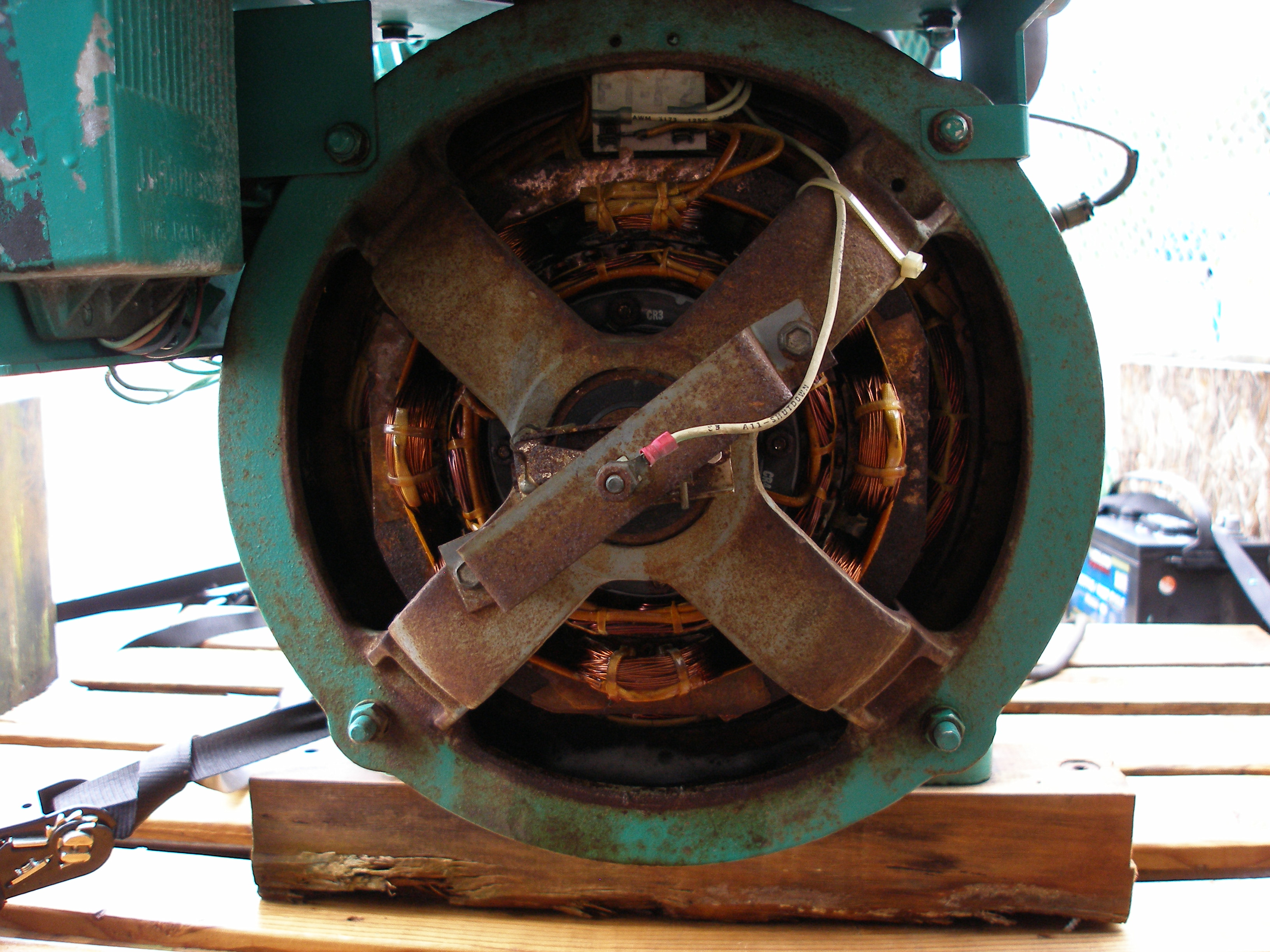
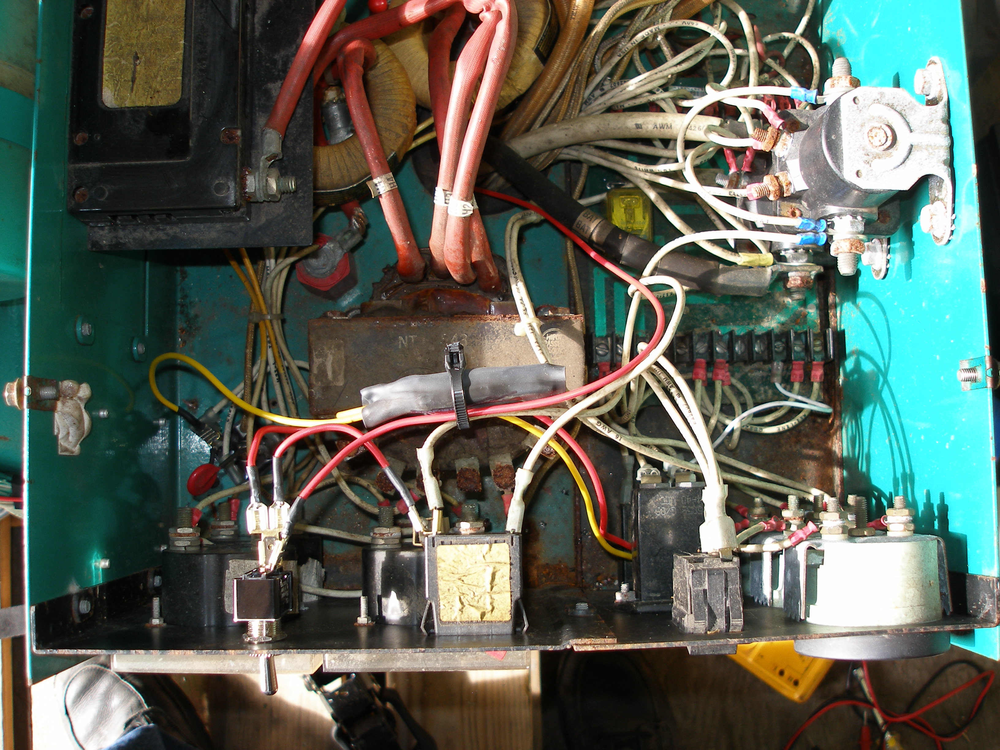
Backed the trailer into our shop, started poking around. This'll make you think twice . . .
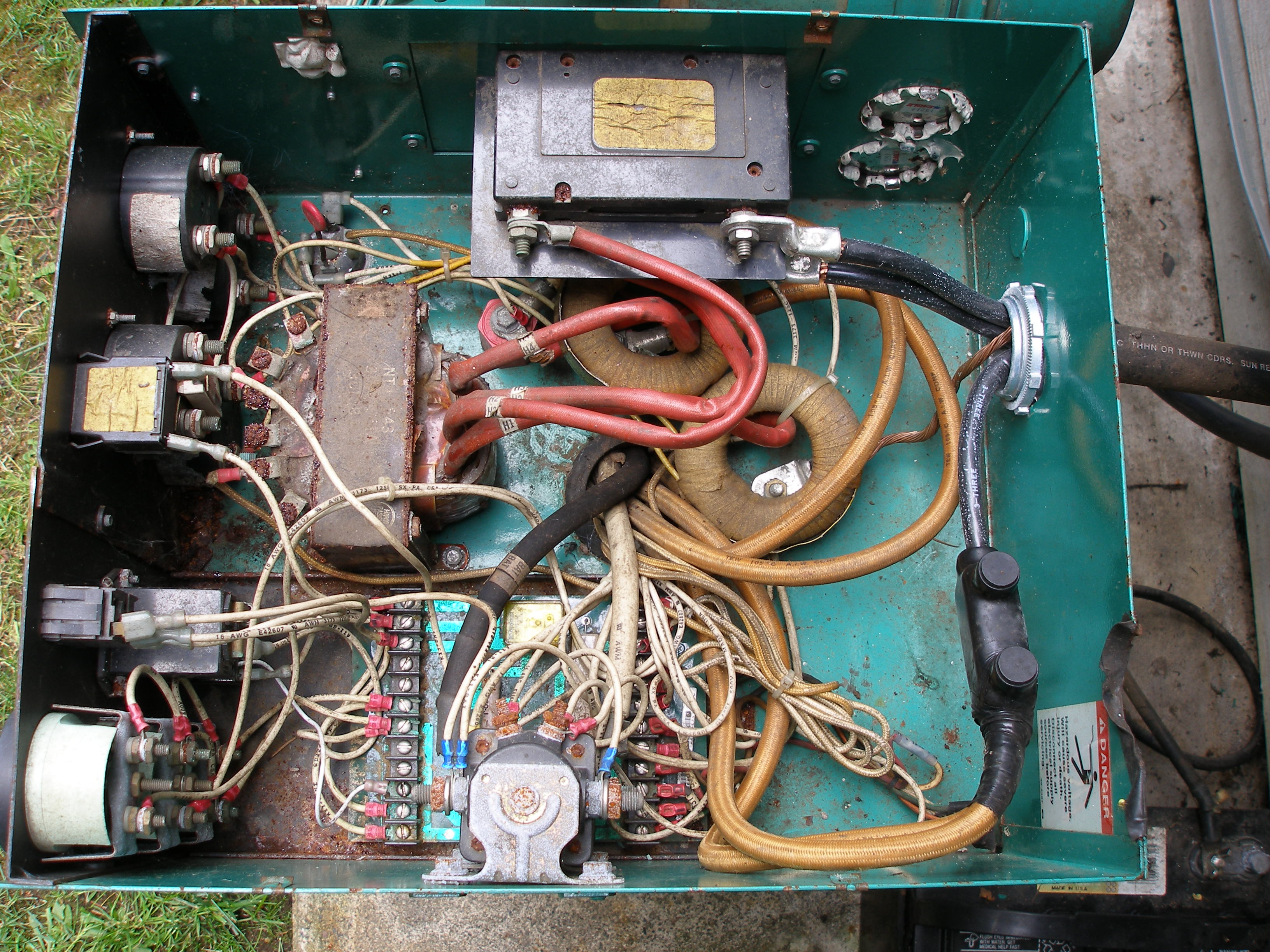
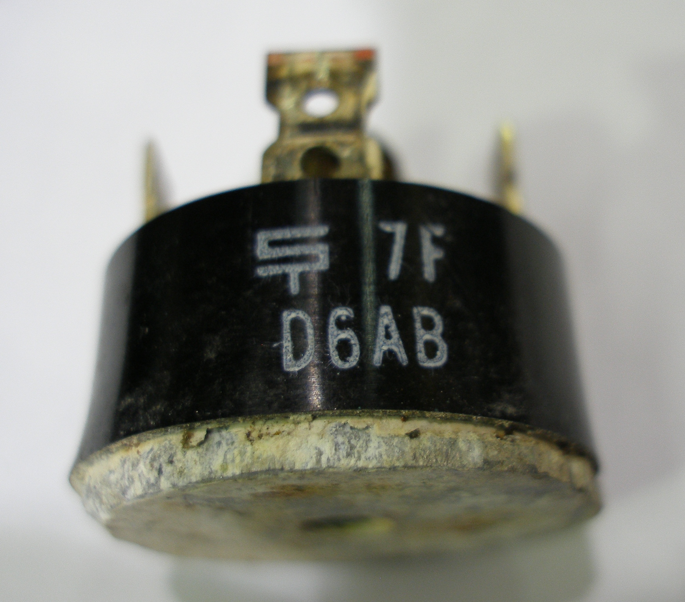
Started probing around, checking diodes (a high failure item on this kind of equipment after 20 yrs), and found this little beauty bad -- bridge rectifier to feed the fixed field coils:
Still Sunday afternoon, so I drive to storage seven miles away, and yard out a adequate-looking bridge from an old monitor board (I have a few):
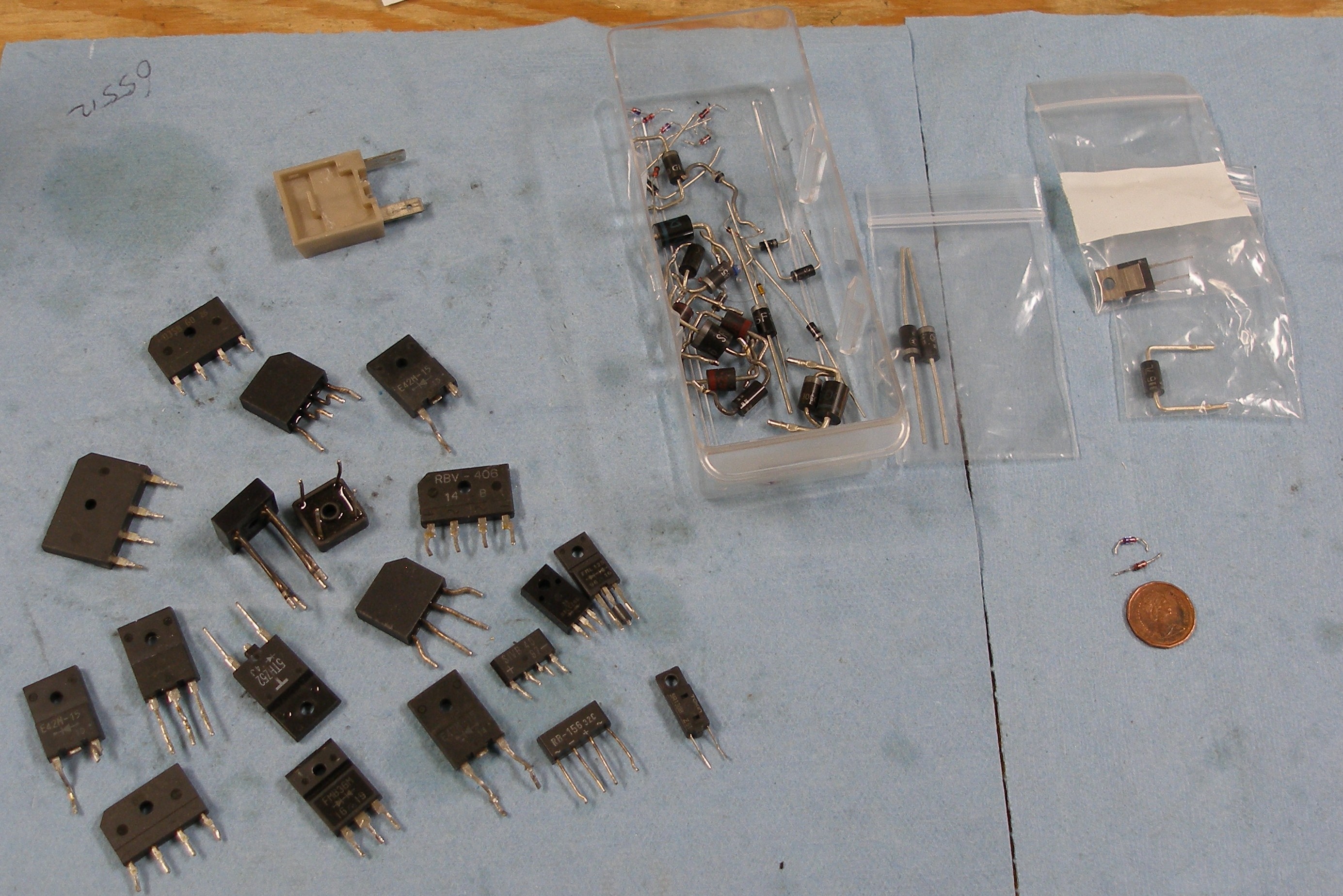
. . . and soldered on a few leads and connectors . . .
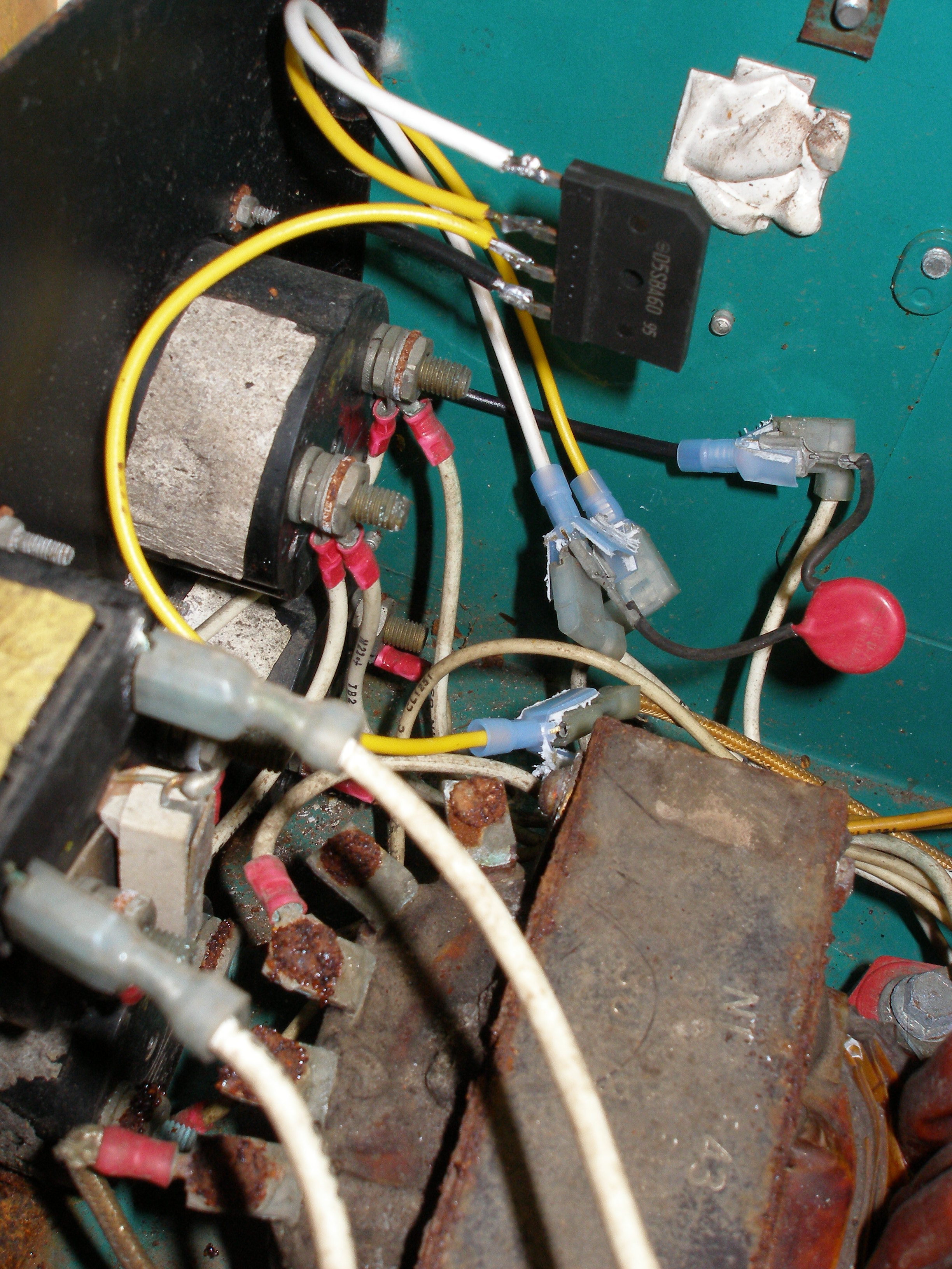
Fired it up, flashed the field coils, and the voltage comes right up! Later, I ordered a more suitable bridge from Mouser.com, a 35A unit.

Not too bad, for a $785 savings, eh?
Now, on to the rest of the list for this puppy.
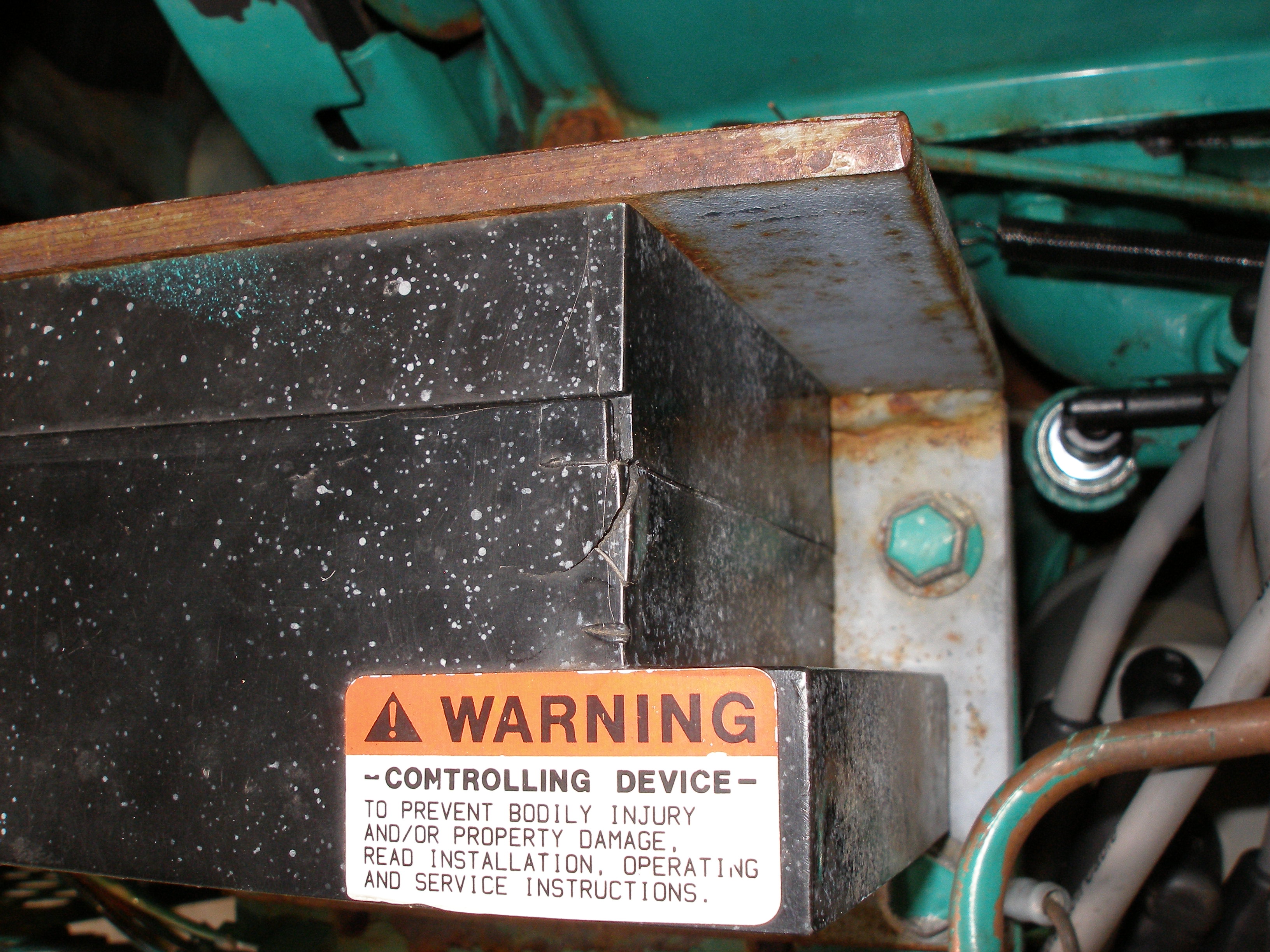
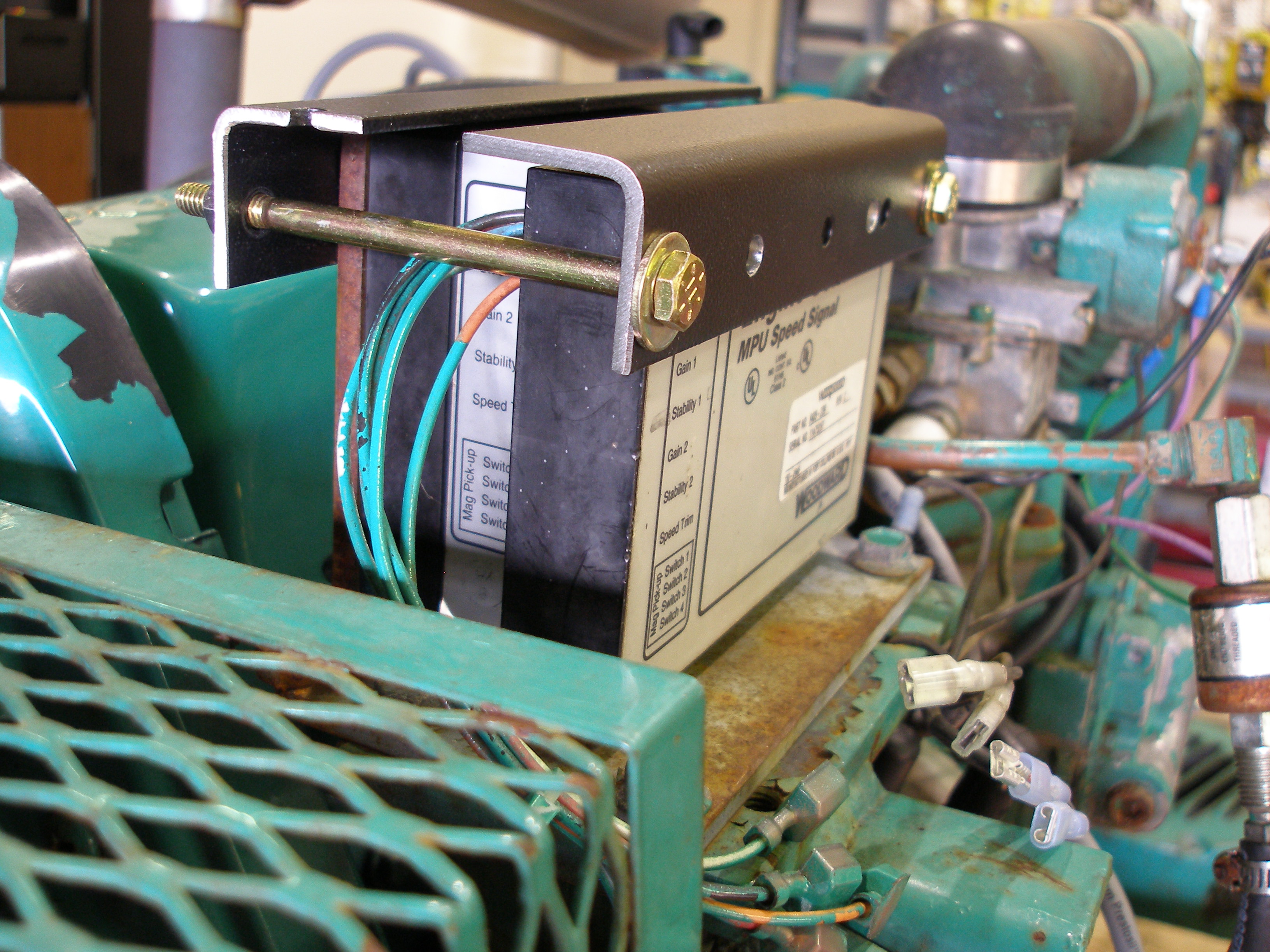
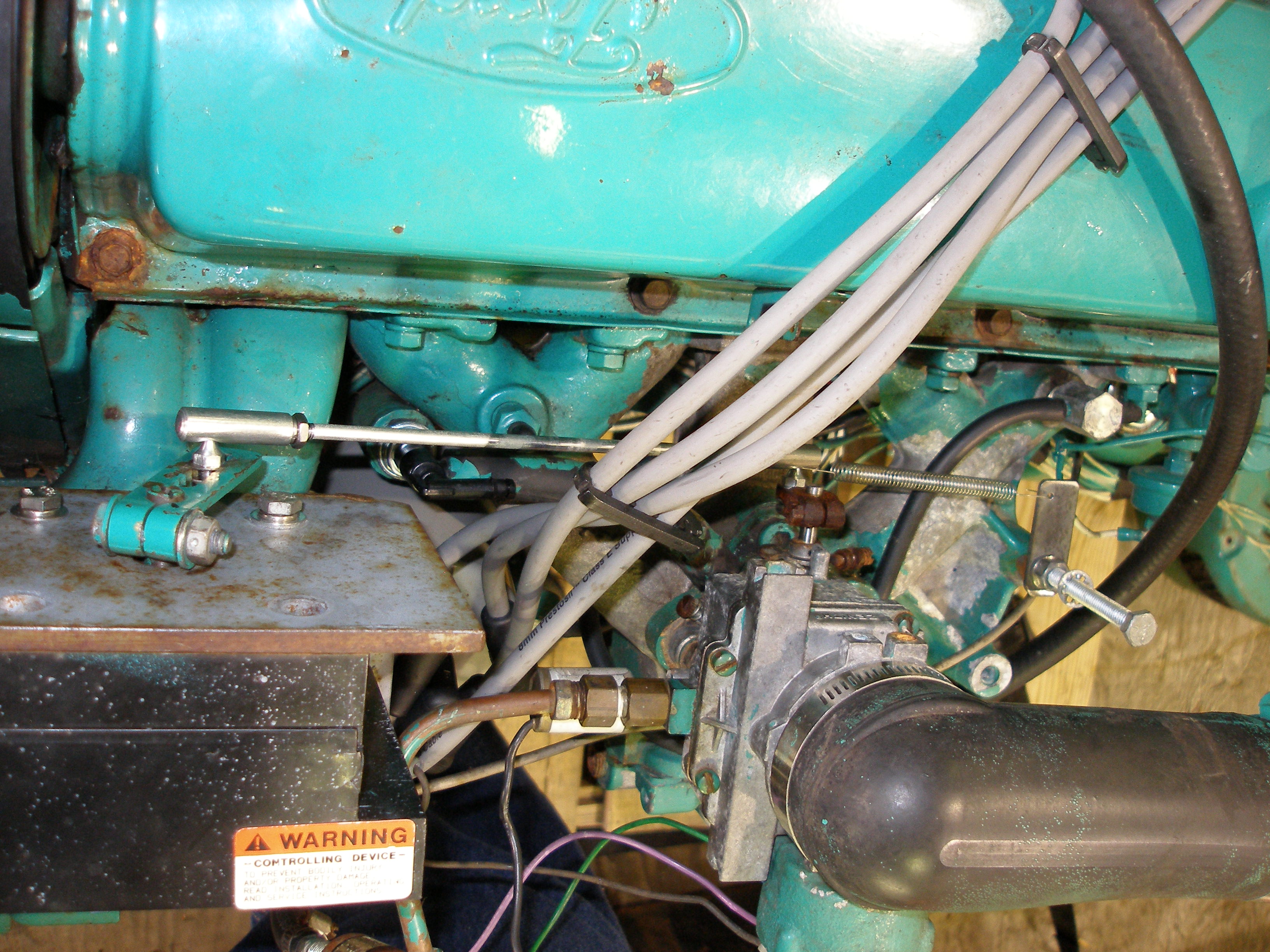
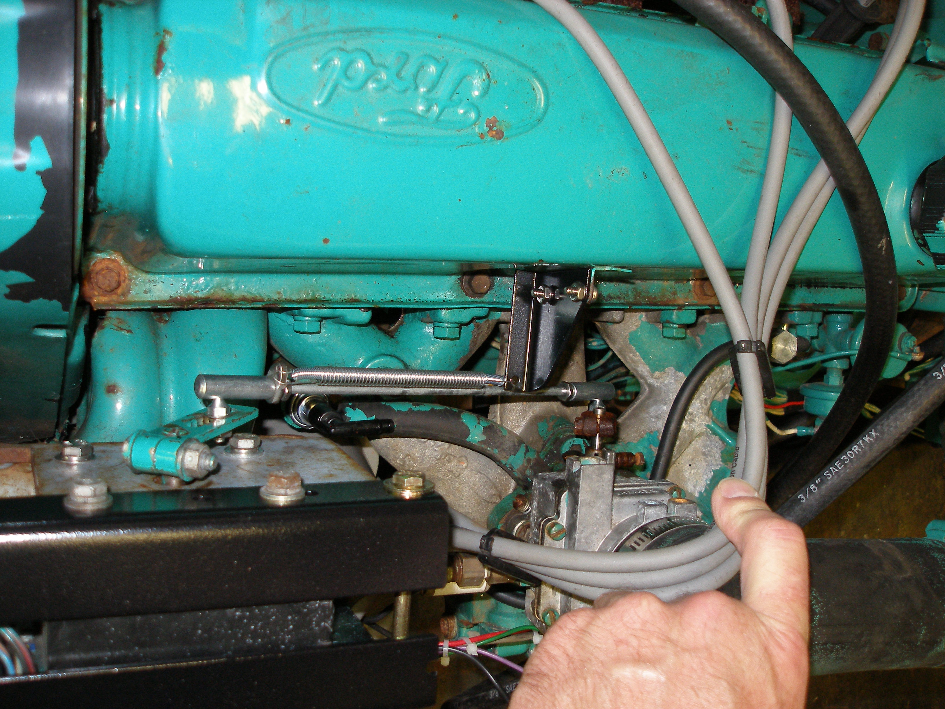
That governor is obviously not an Onan part:
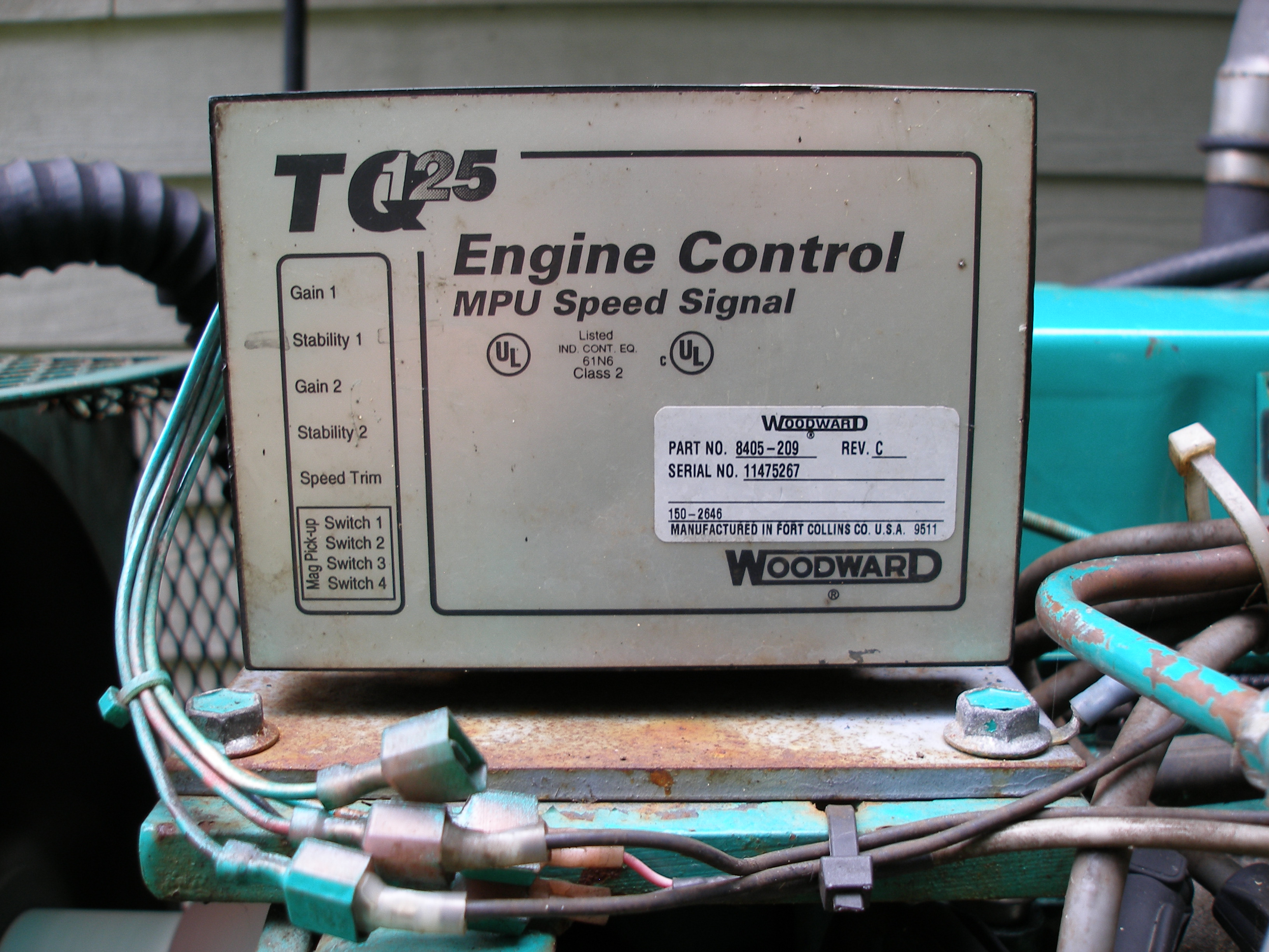
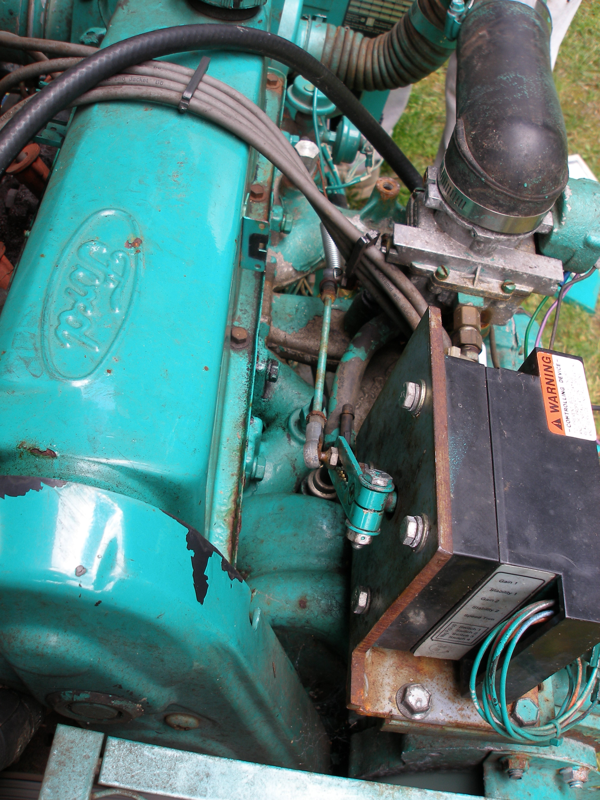
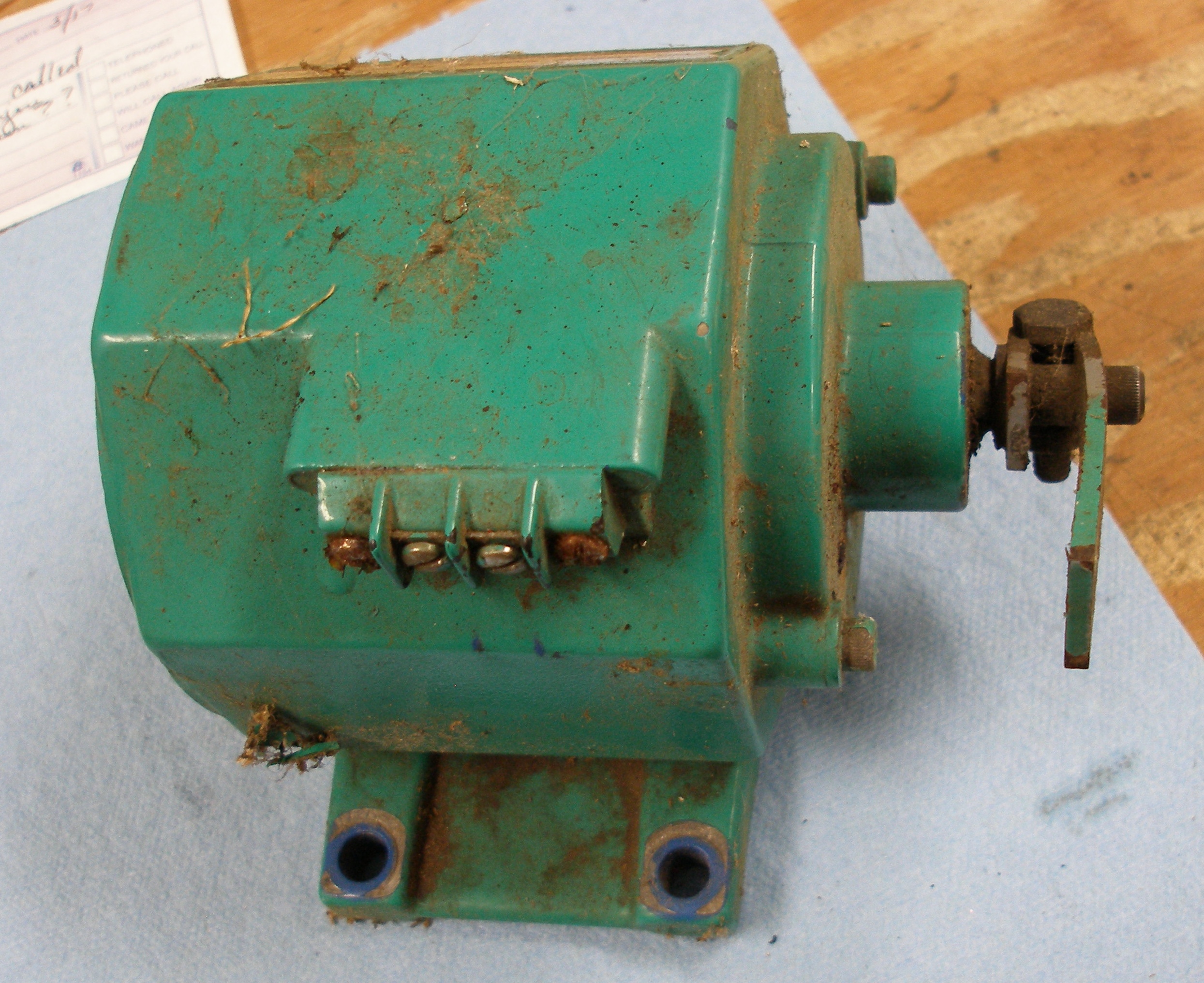
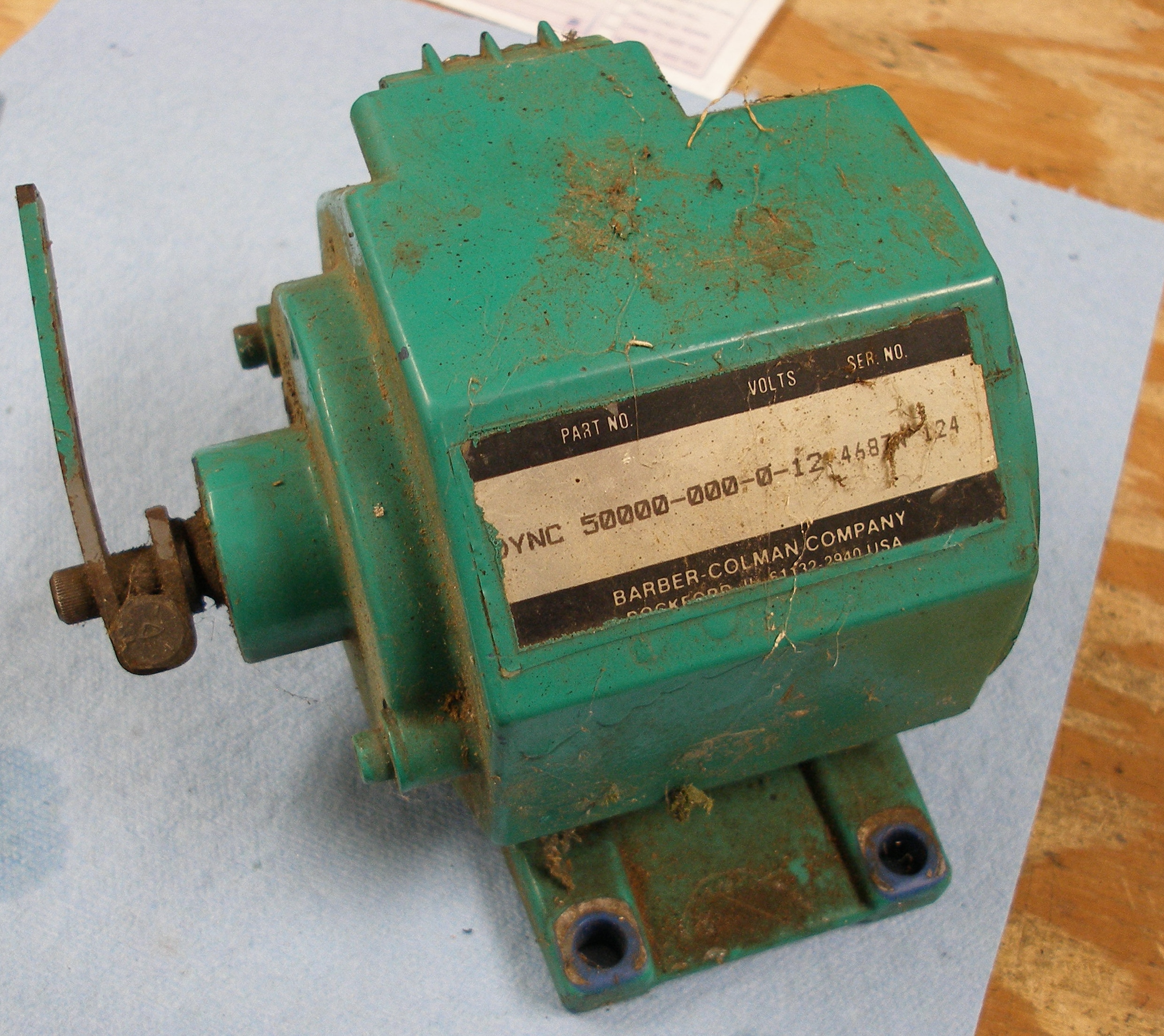
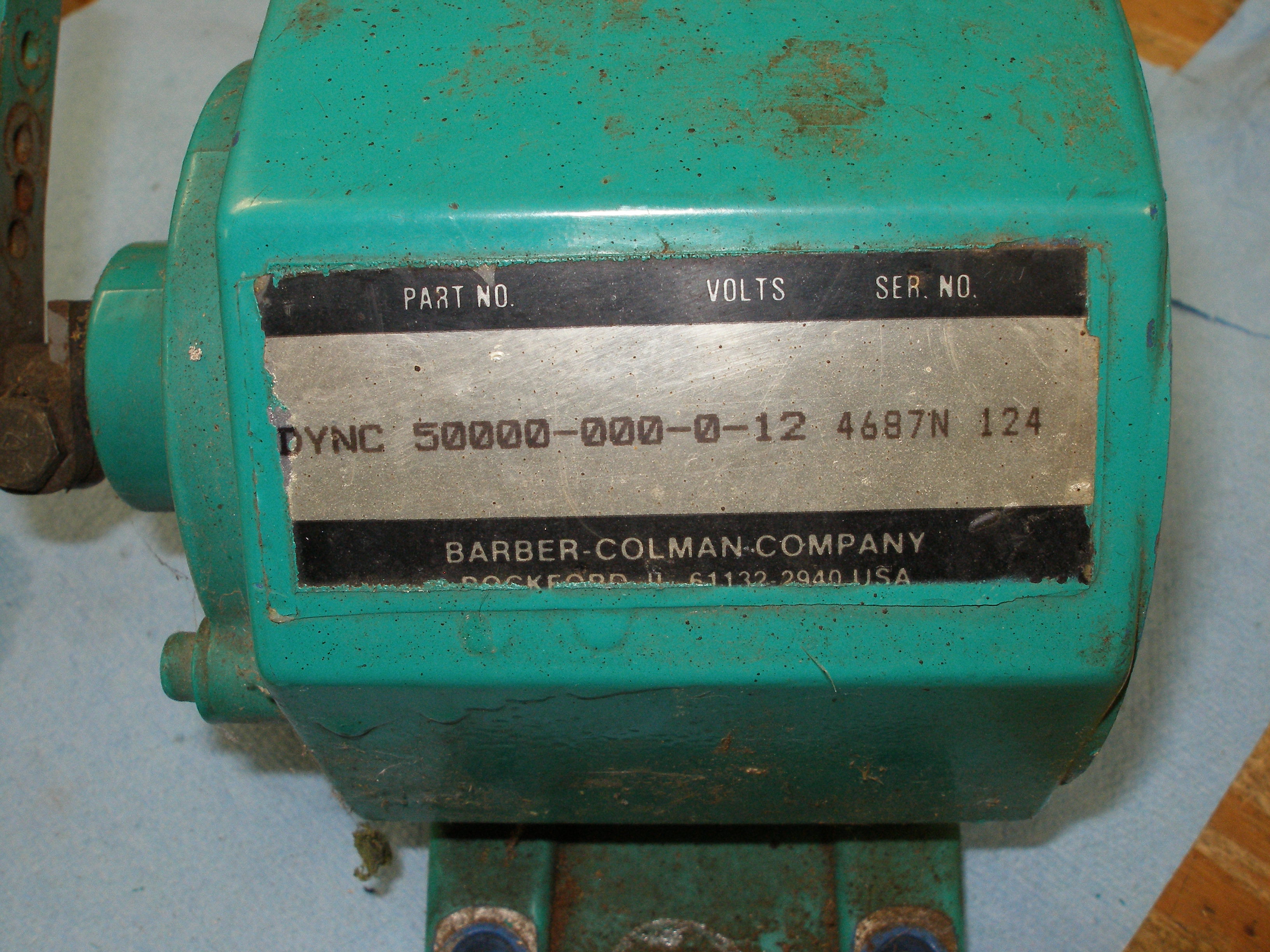
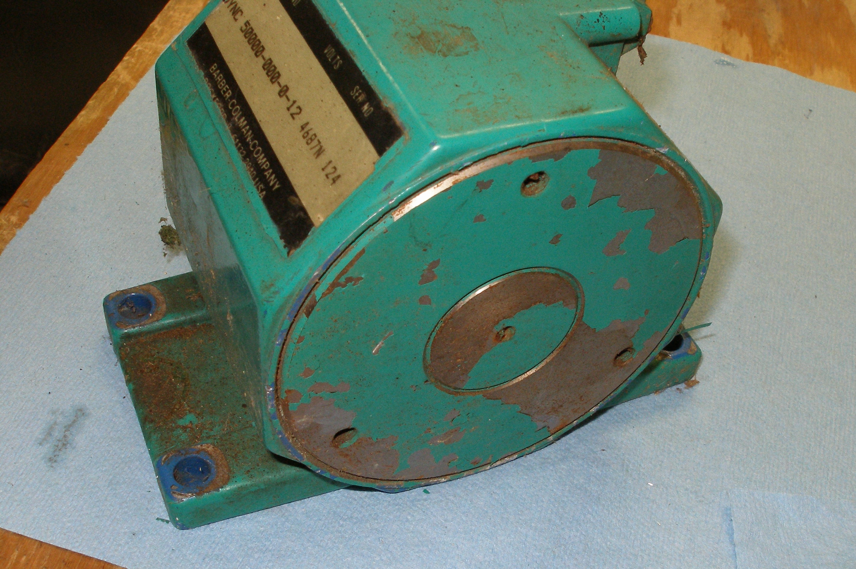
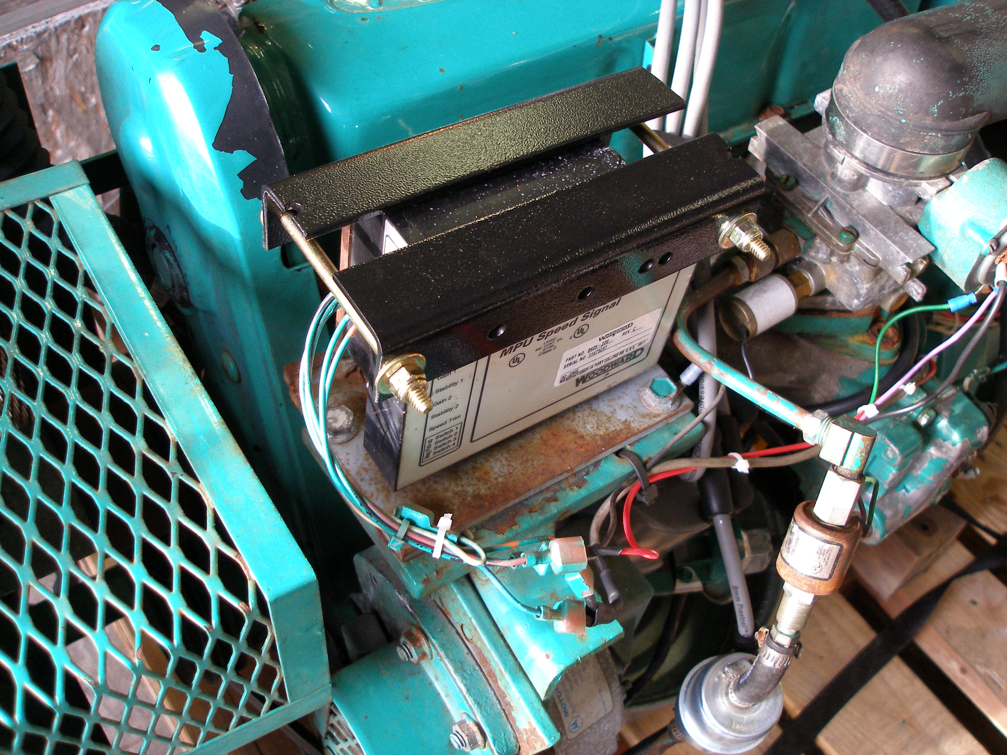
It's a Woodward TQ-125, all-in-one unit, as opposed to the two-piece Barber-Coleman that somebody took off the actuator and put in a box:
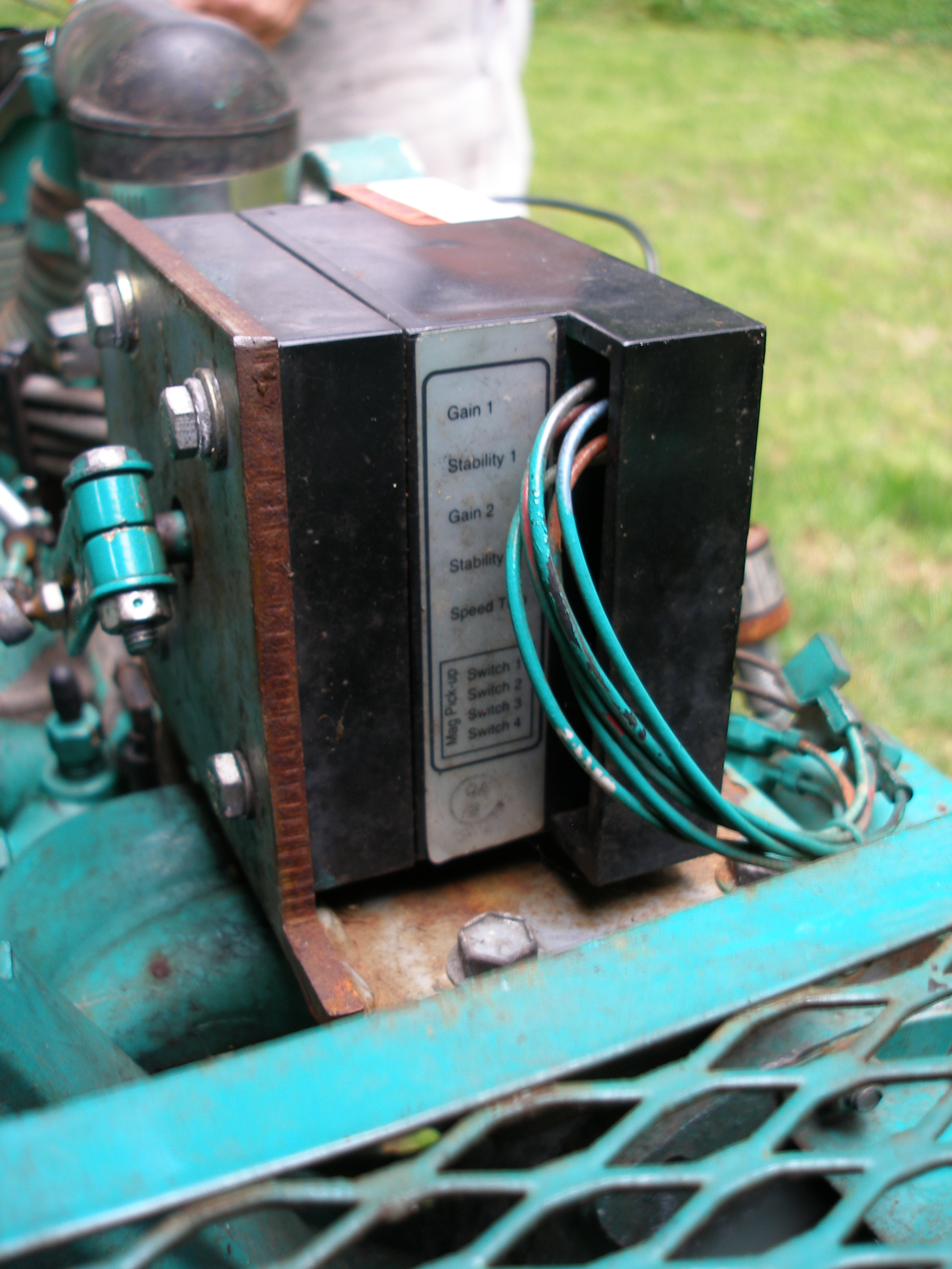
The Woodward has some structural weaknesses, and the linkage is kaput:
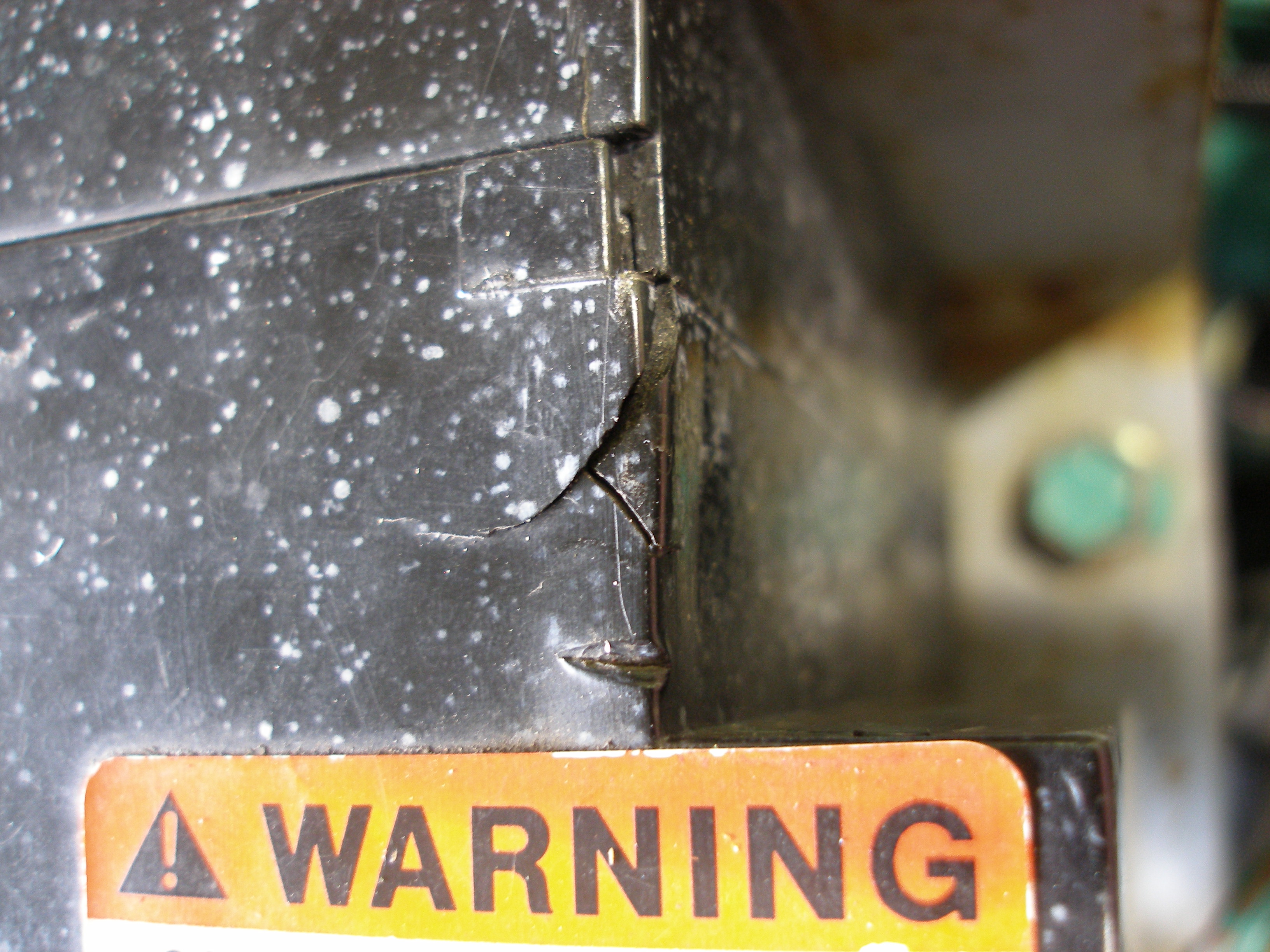
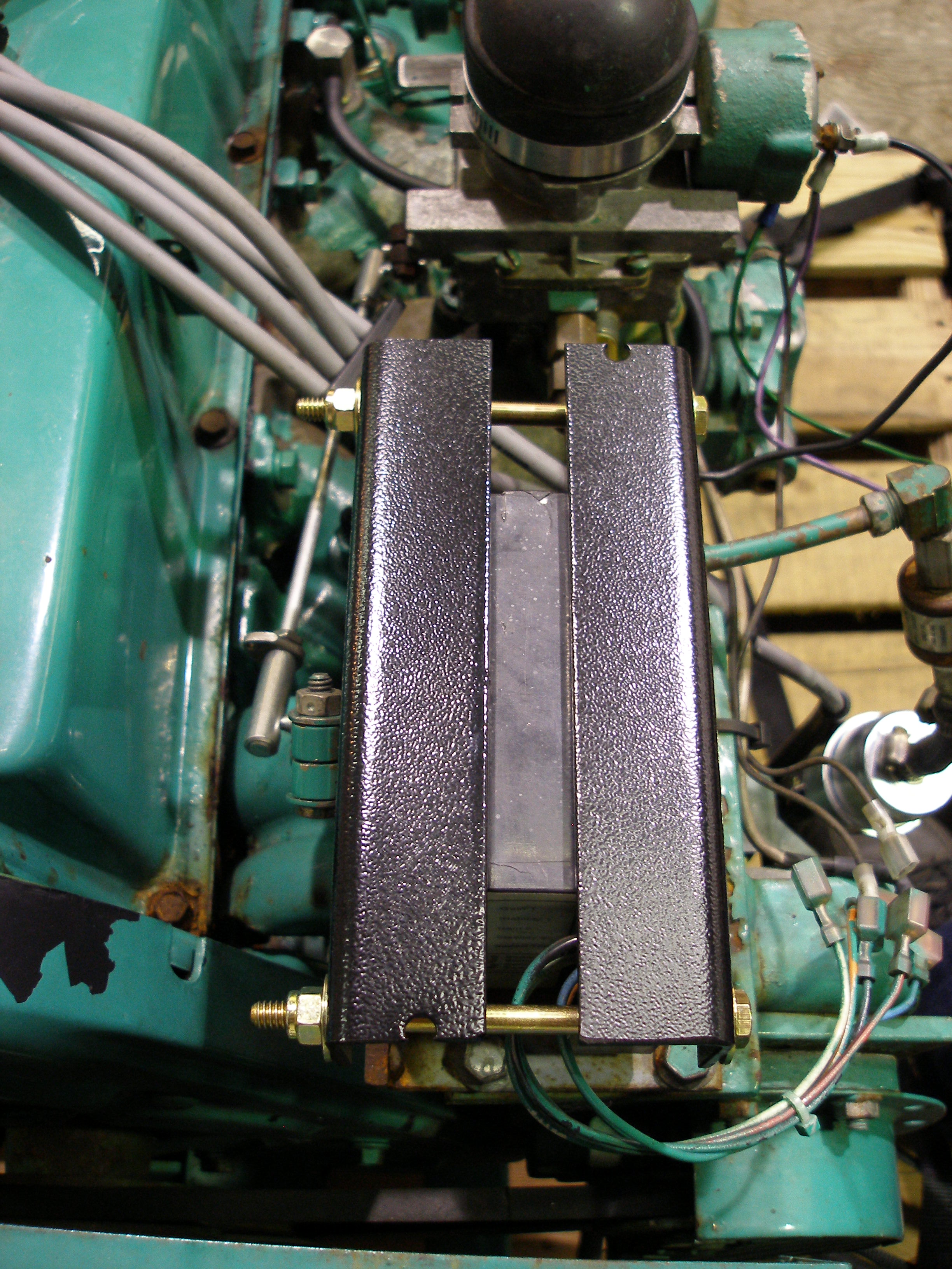
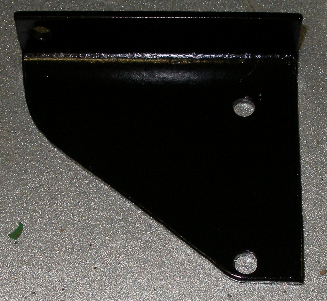
Because the four mounting screws that retain the TQ-125 to the engine do not actually go all the way into the rear case, I had to come up with a method to stabilize the assy. without through bolts. I went for a sandwich:

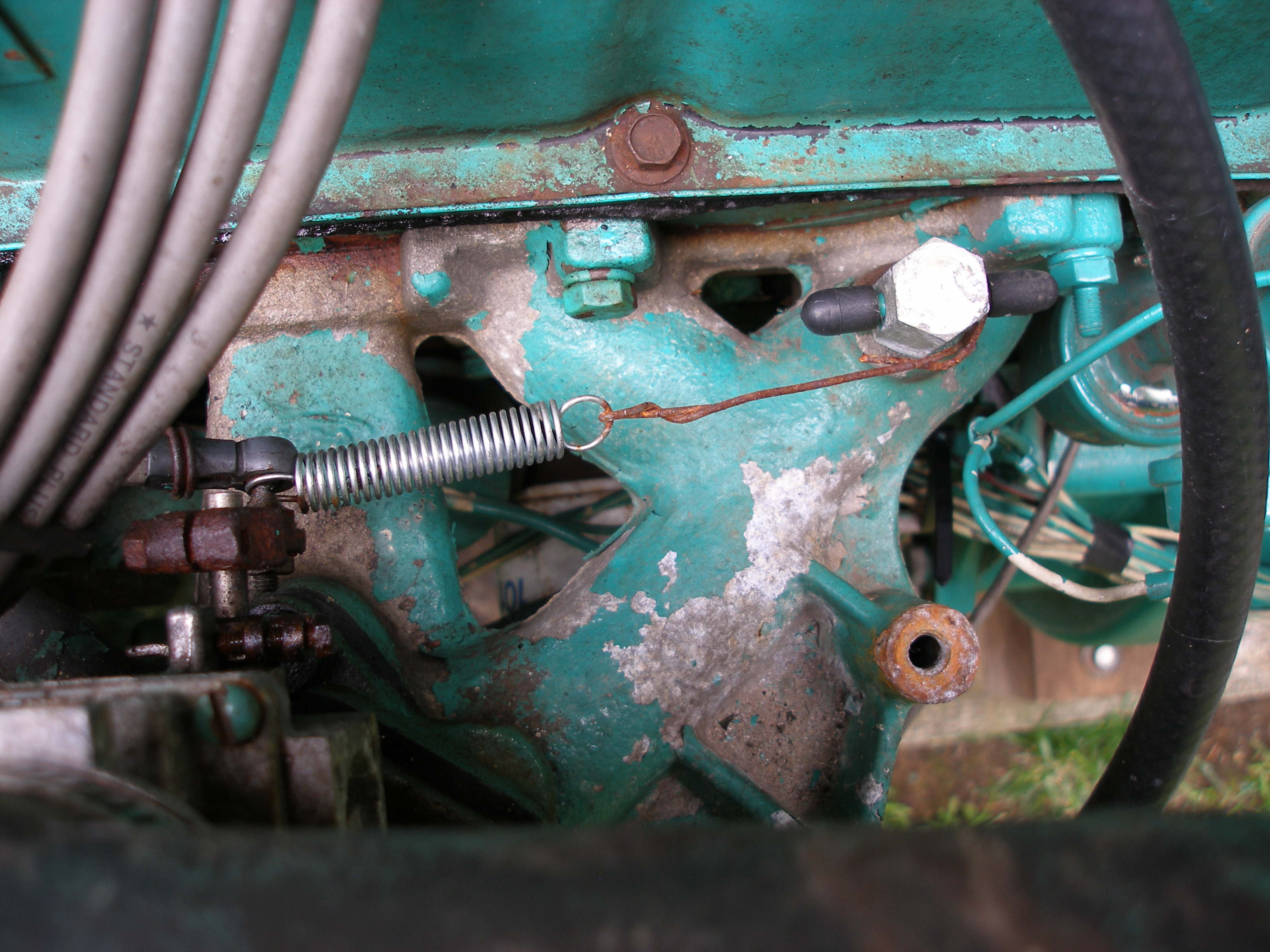
Mock-up of the new linkage. The old one had plastic joint ends wrapped with wire to hold them on!
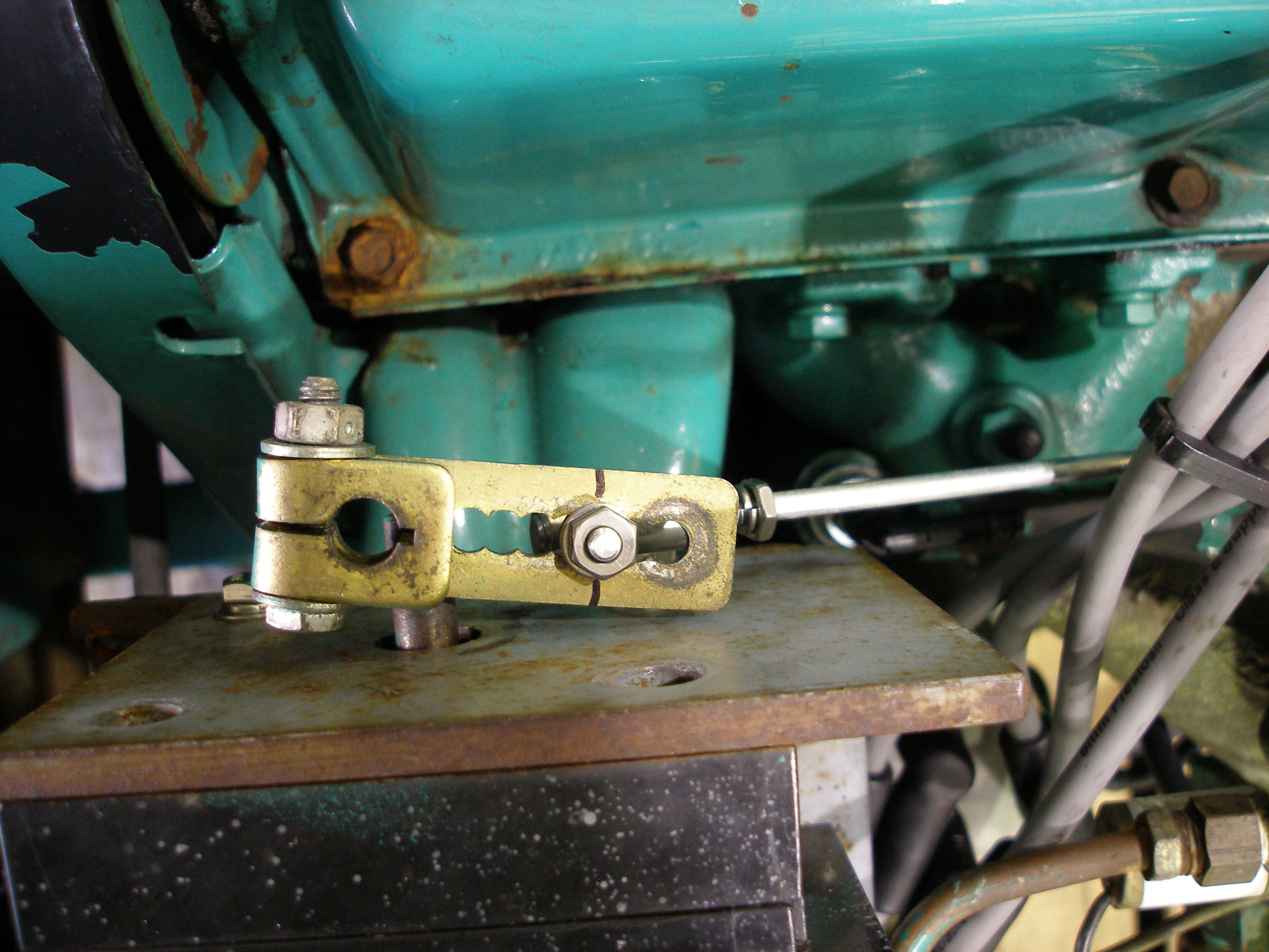
Need a better way to pull on the linkage than interfering with the ball end:

A new spring anchor:
More-or-less finished linkage, with new spring anchors, rod, and ball joints.
After repainting the clamps:
It's not obvious, but there are two linkage return springs, one inside the other.
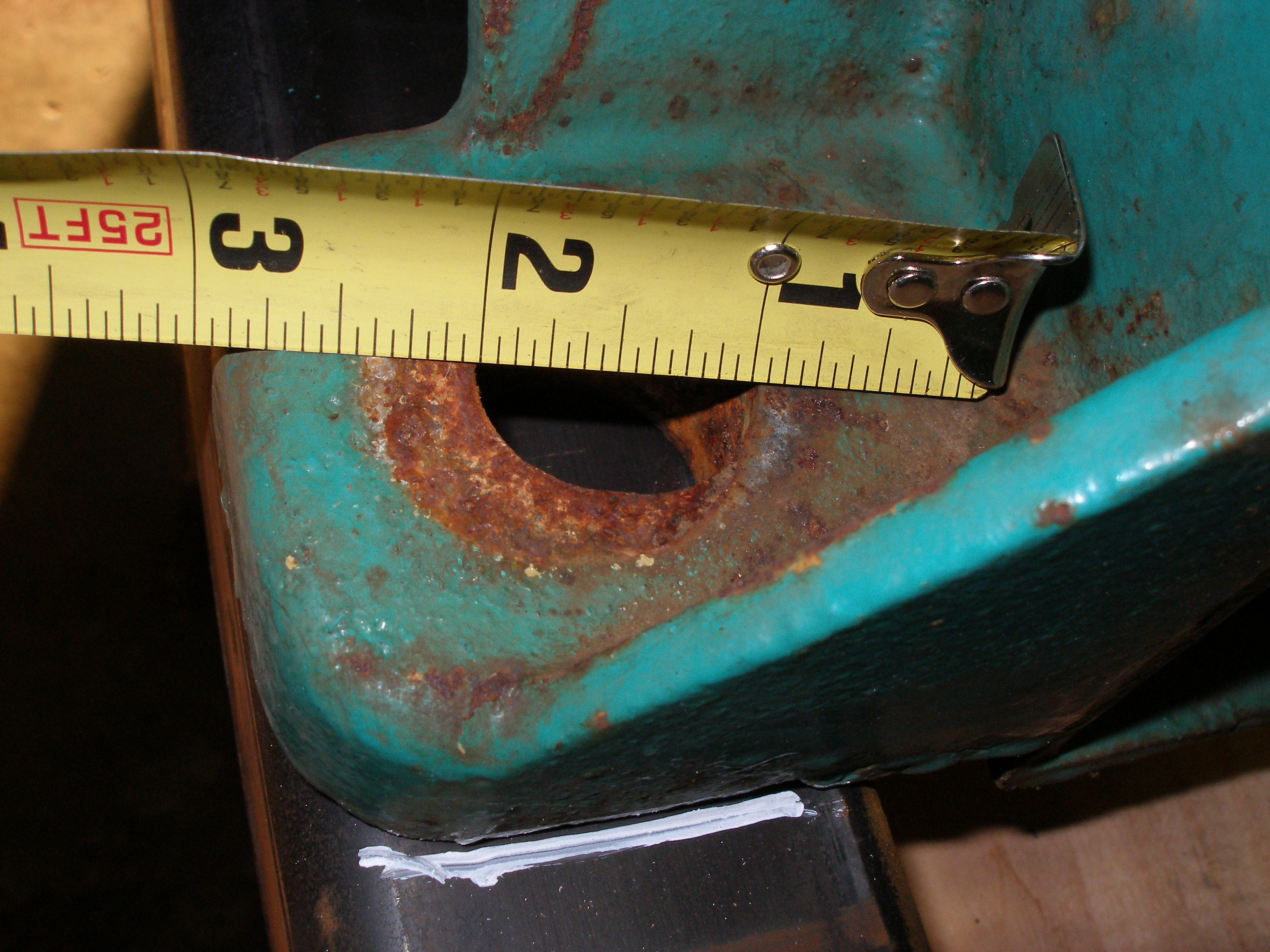
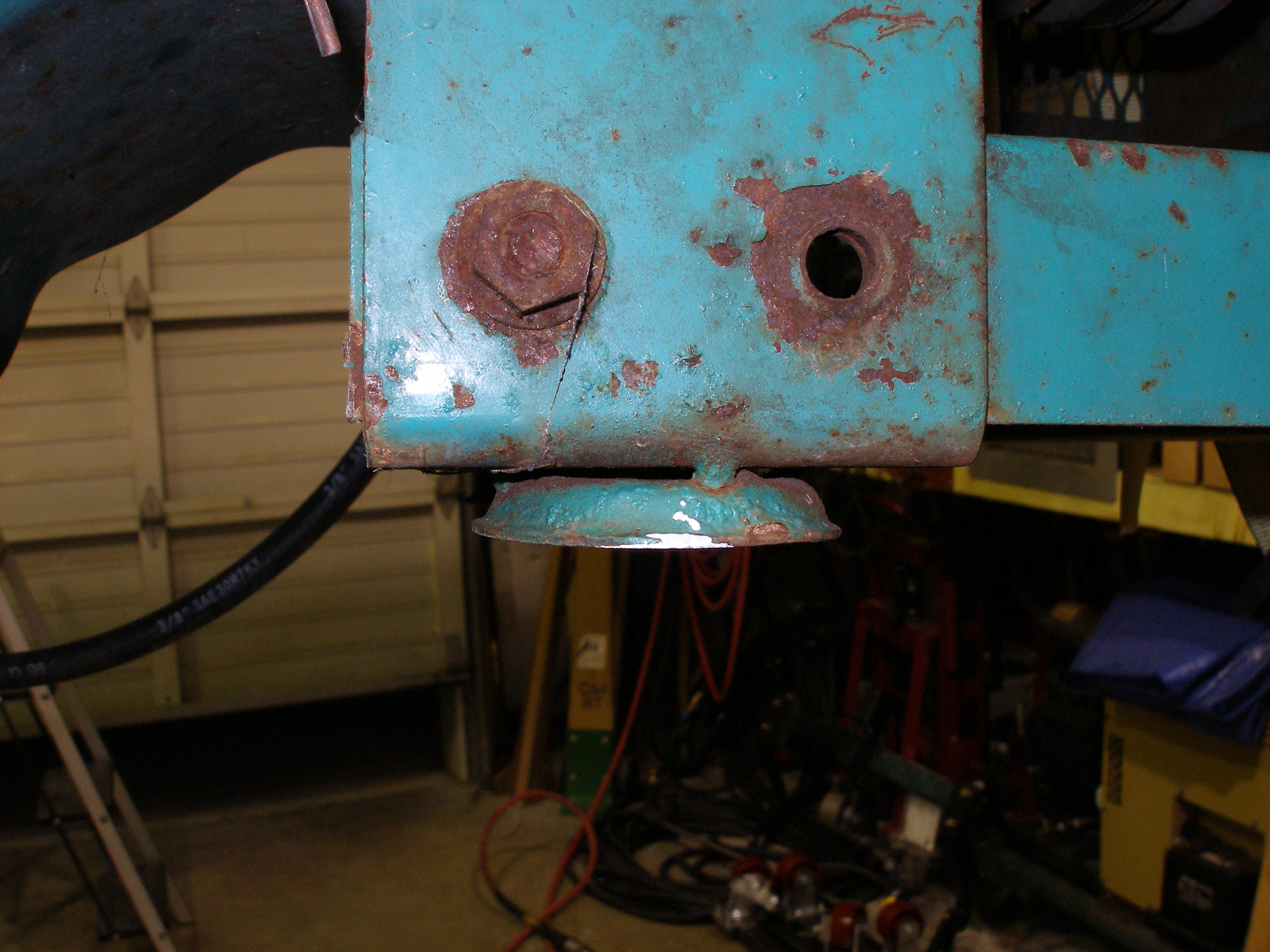
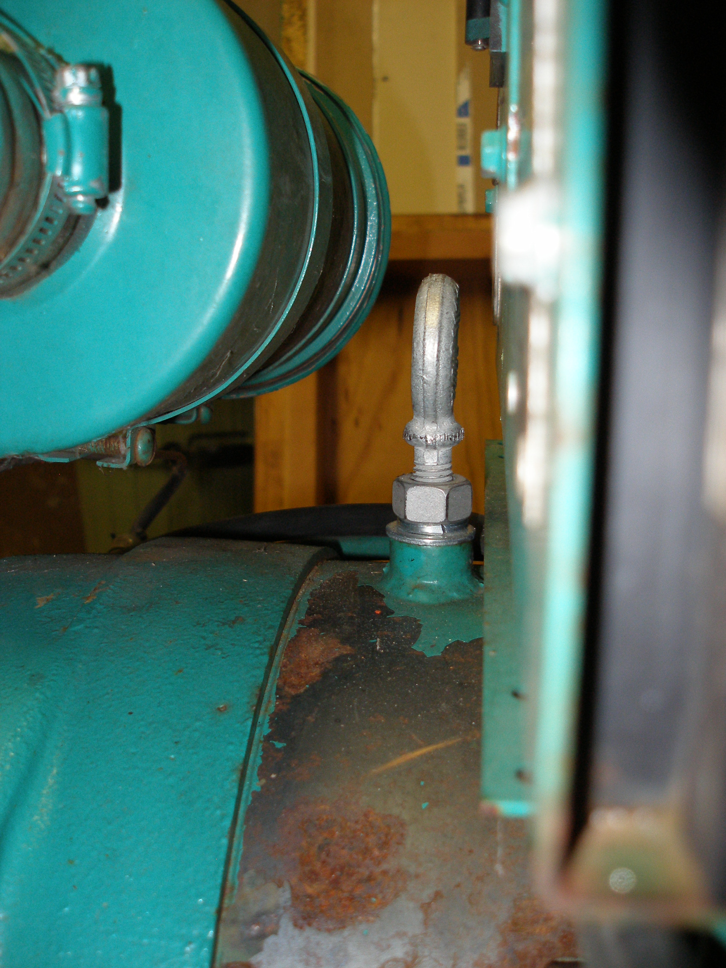
Next, I added a lift eye to the generator. The casing has a 1/2-13 tapped hole, but it's not very long and this one was rusty. I ran a tap down it and blew out all the crud. Because there is very little room in that area, I had to unbolt the controls cabinet and shift it over an inch to allow the eye bolt to rotate.
First install, I put the bolt in this orientation (this pic with the cabinet unbolted and moved rearward:
Unfortunately, when the cabinet is bolted back into place, there is no clearance, and the rubber cabinet mounts were deflected a bit, which cancels their function, so I rotated the eye bolt 90° to fit better.
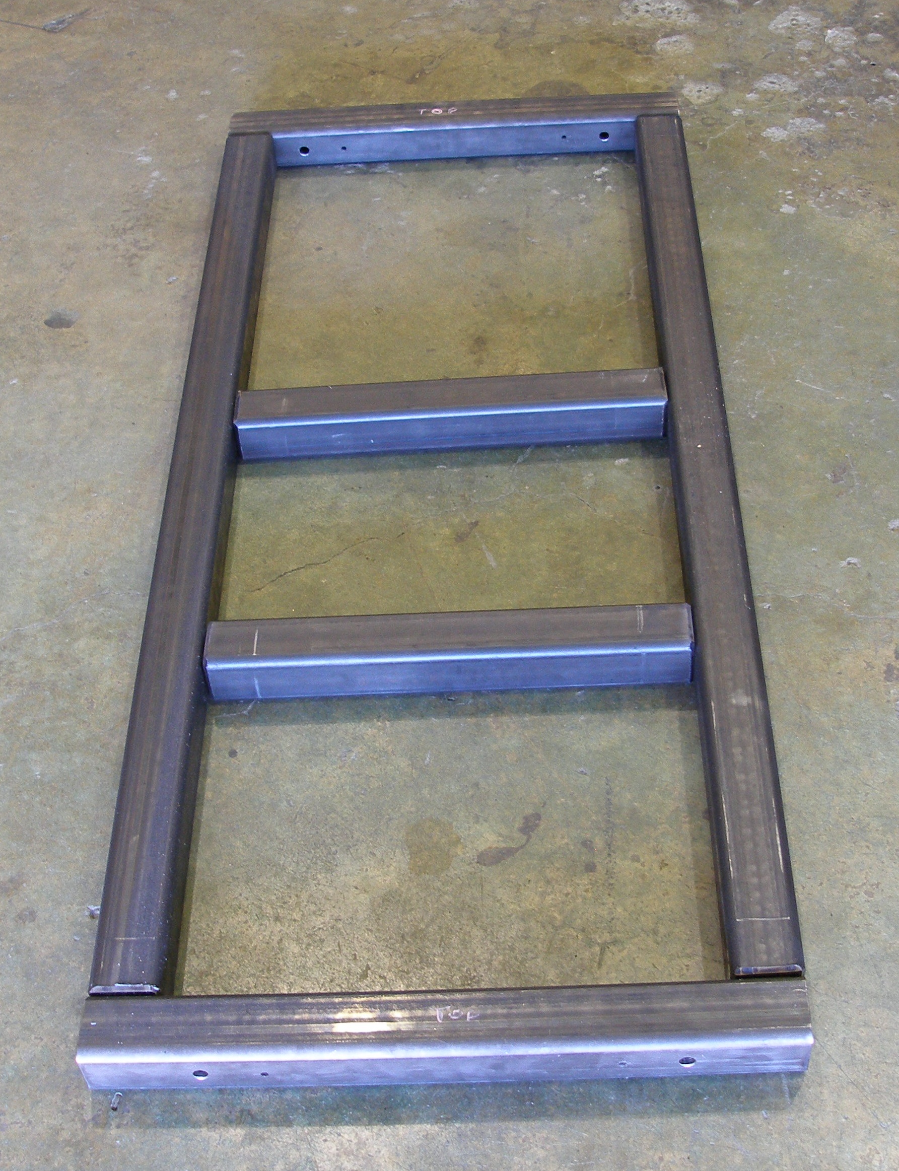
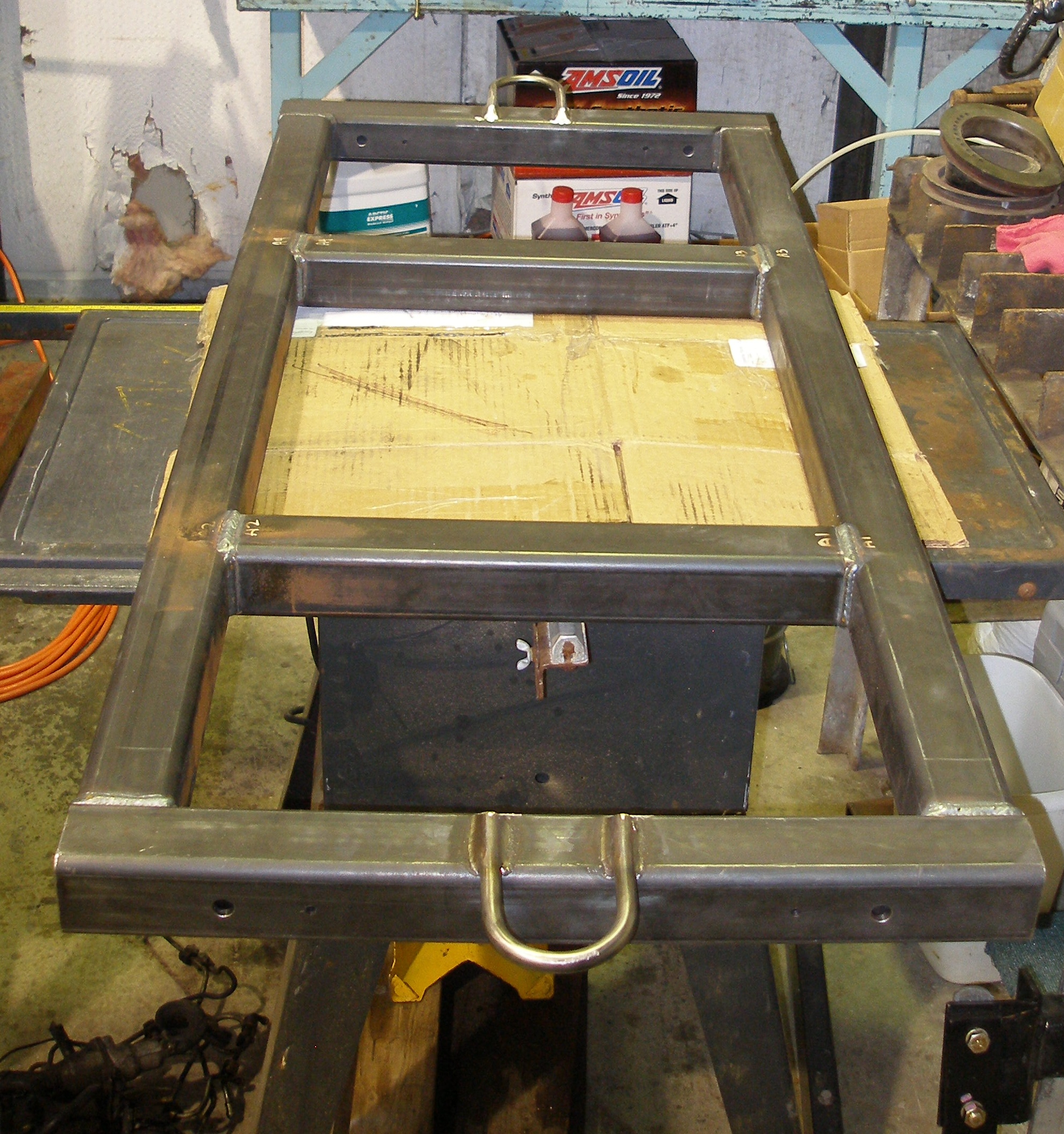
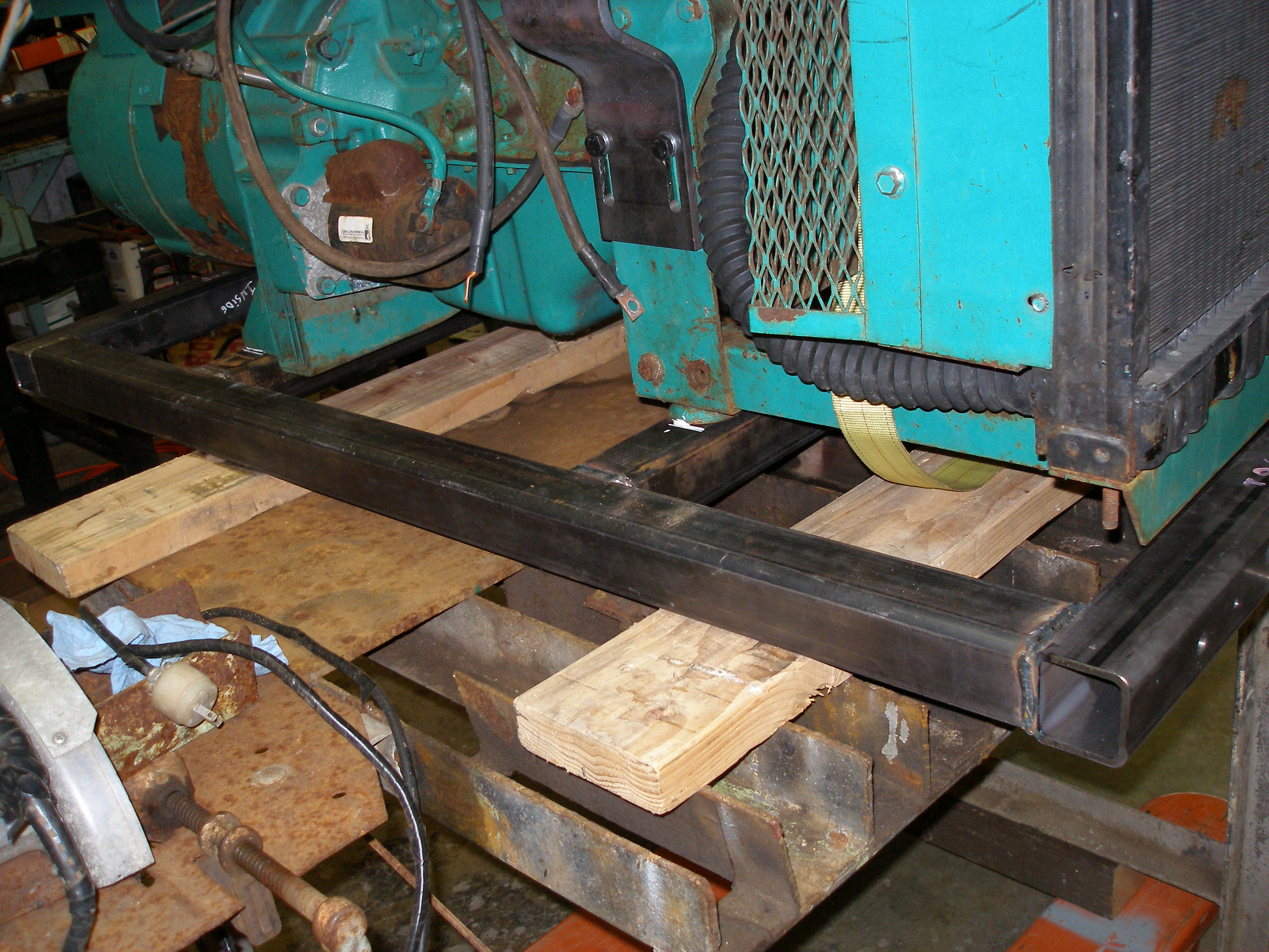
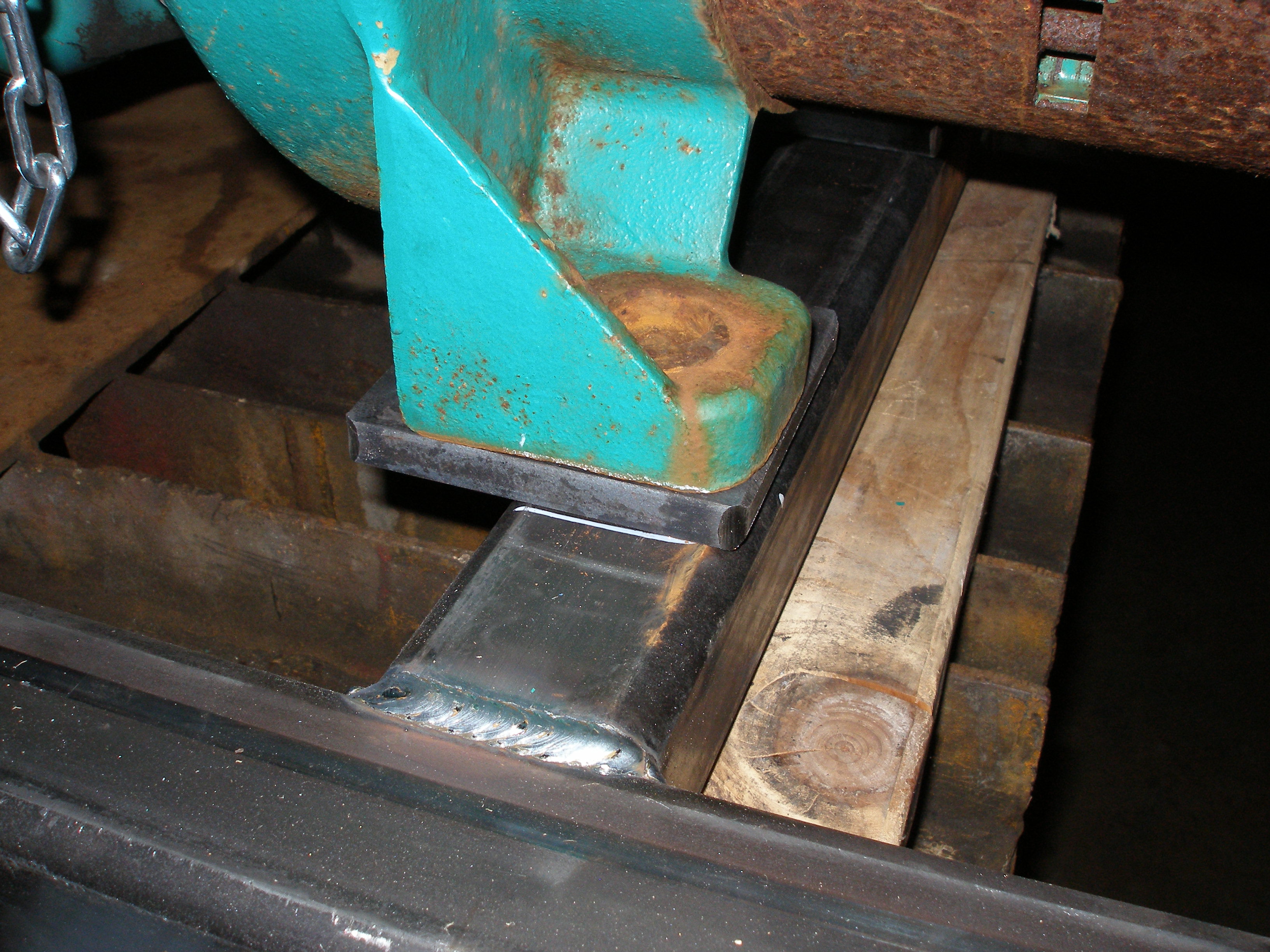
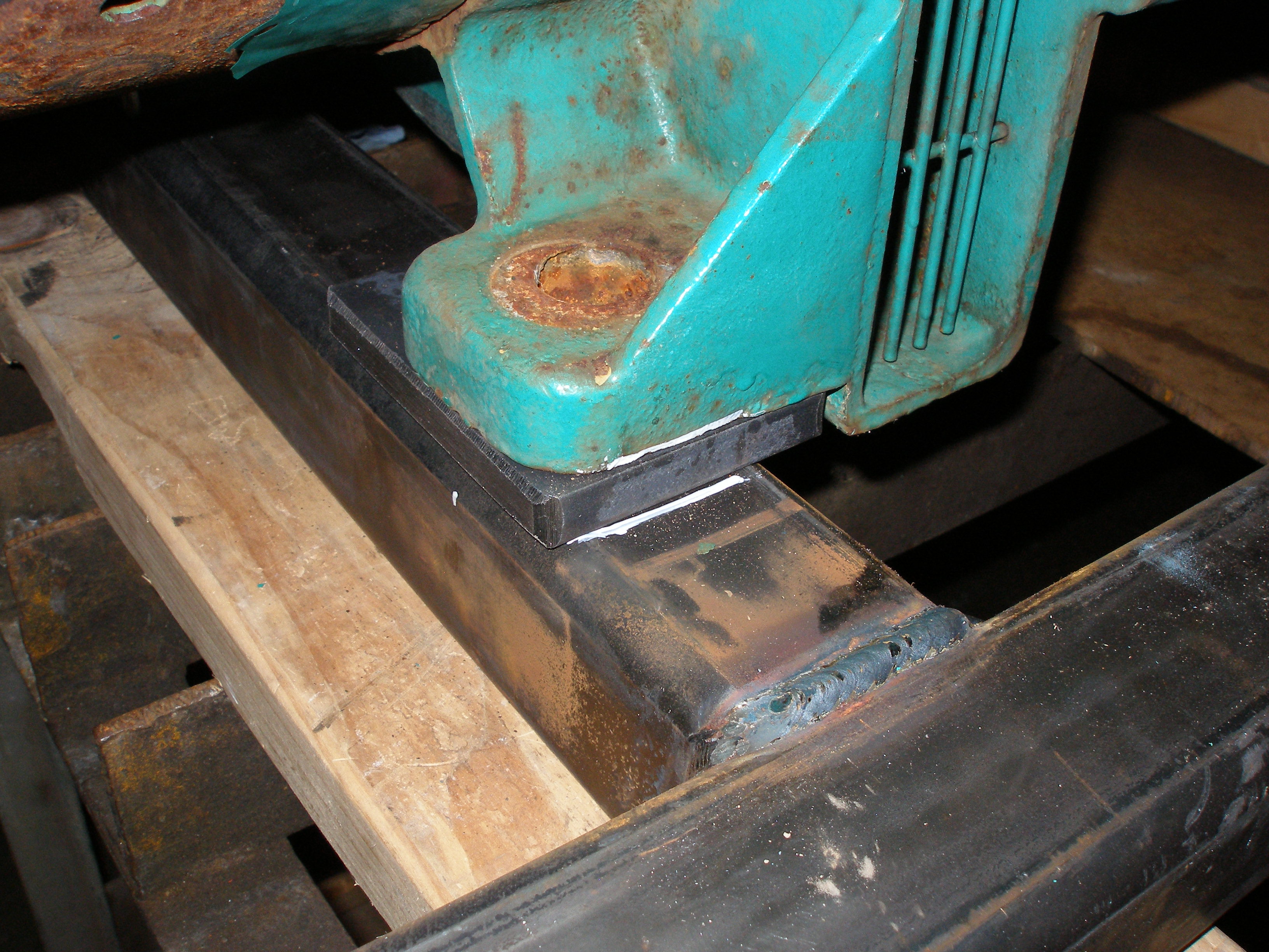
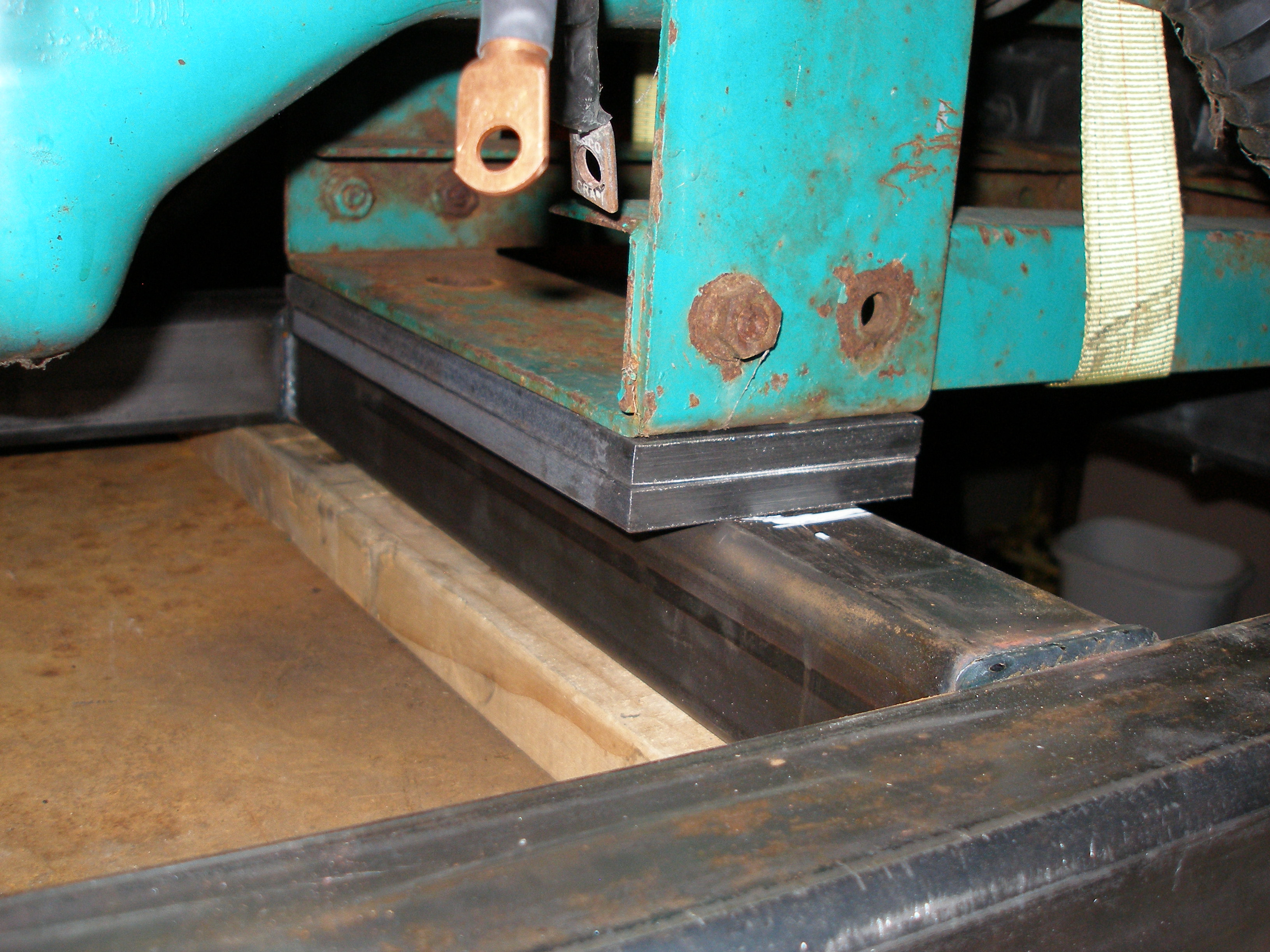
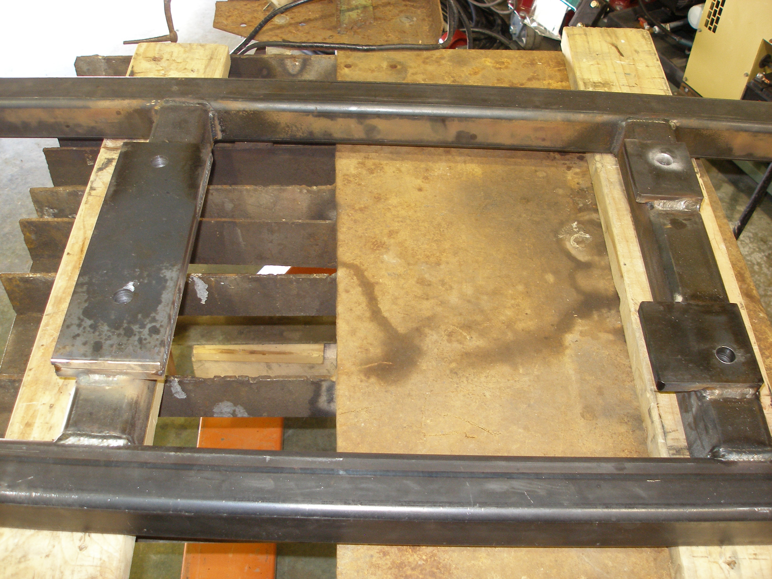
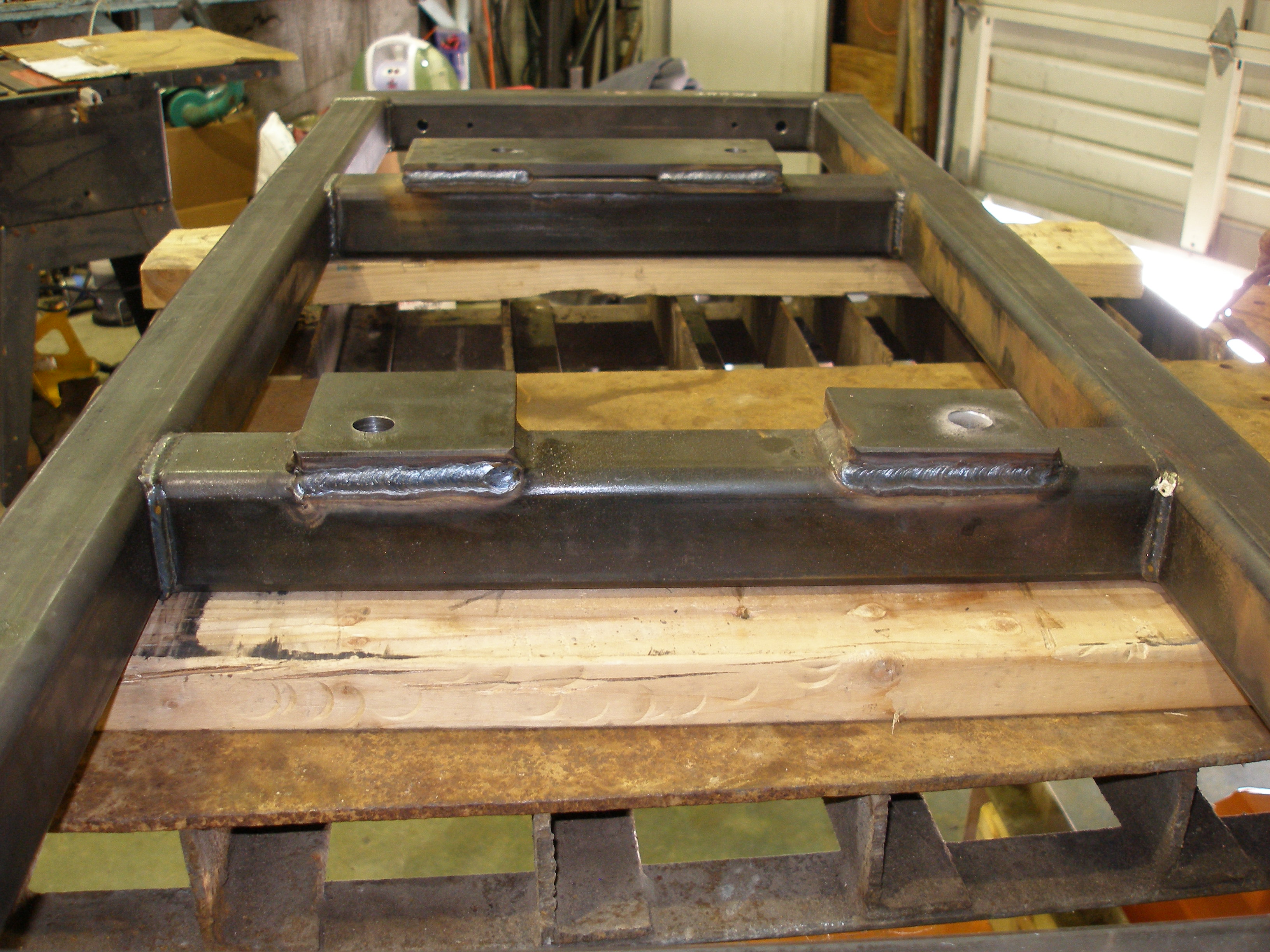
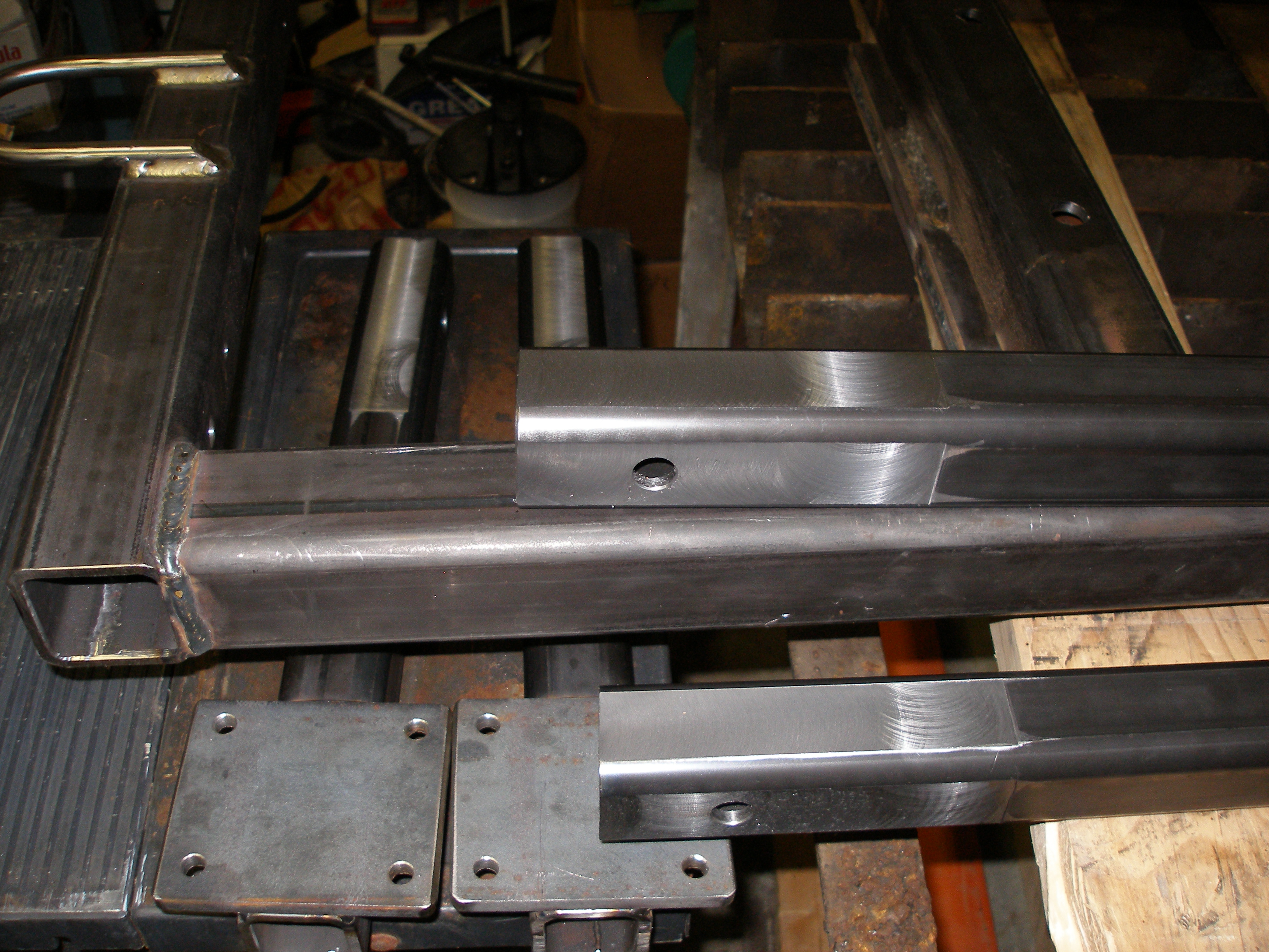
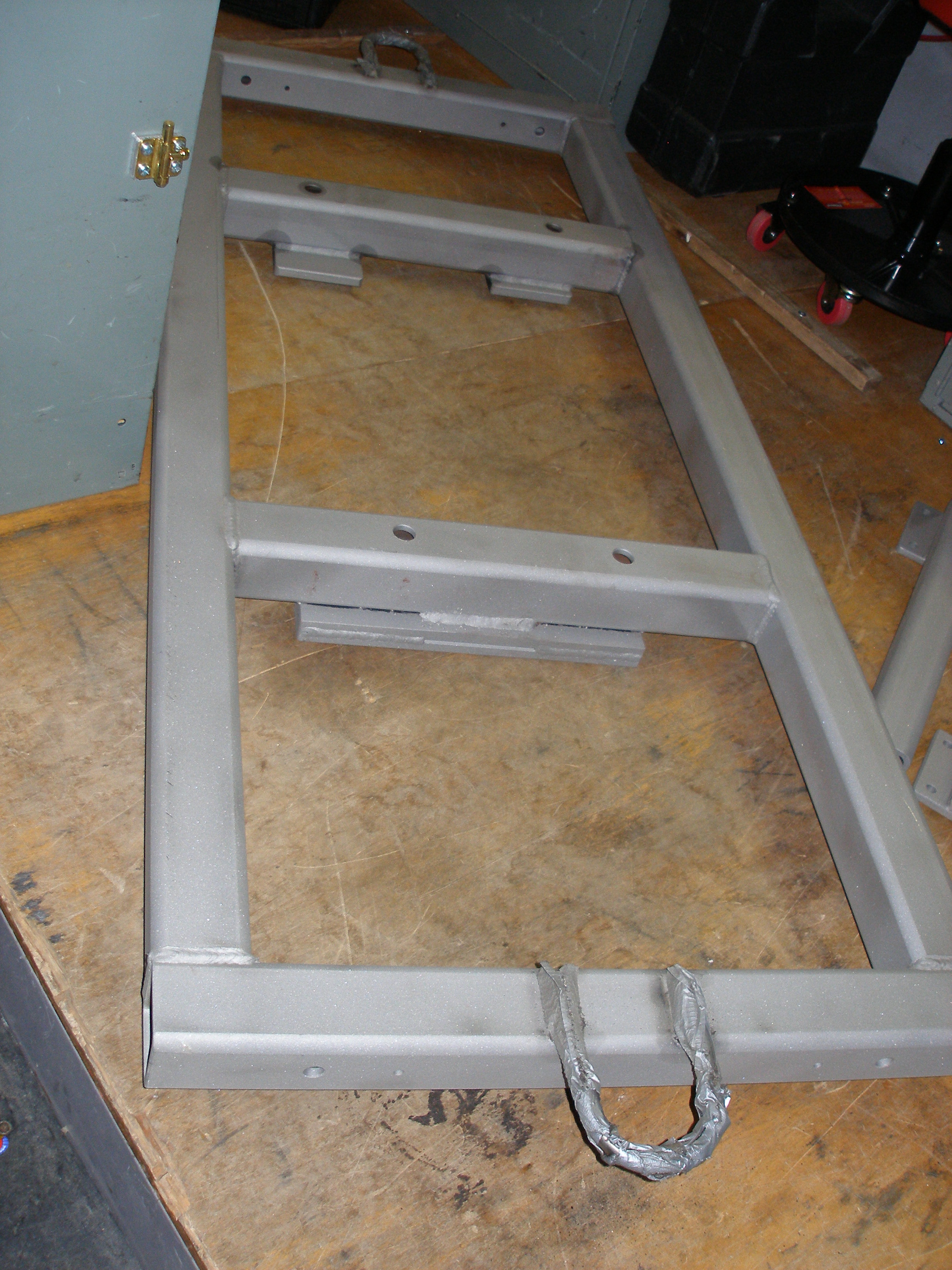
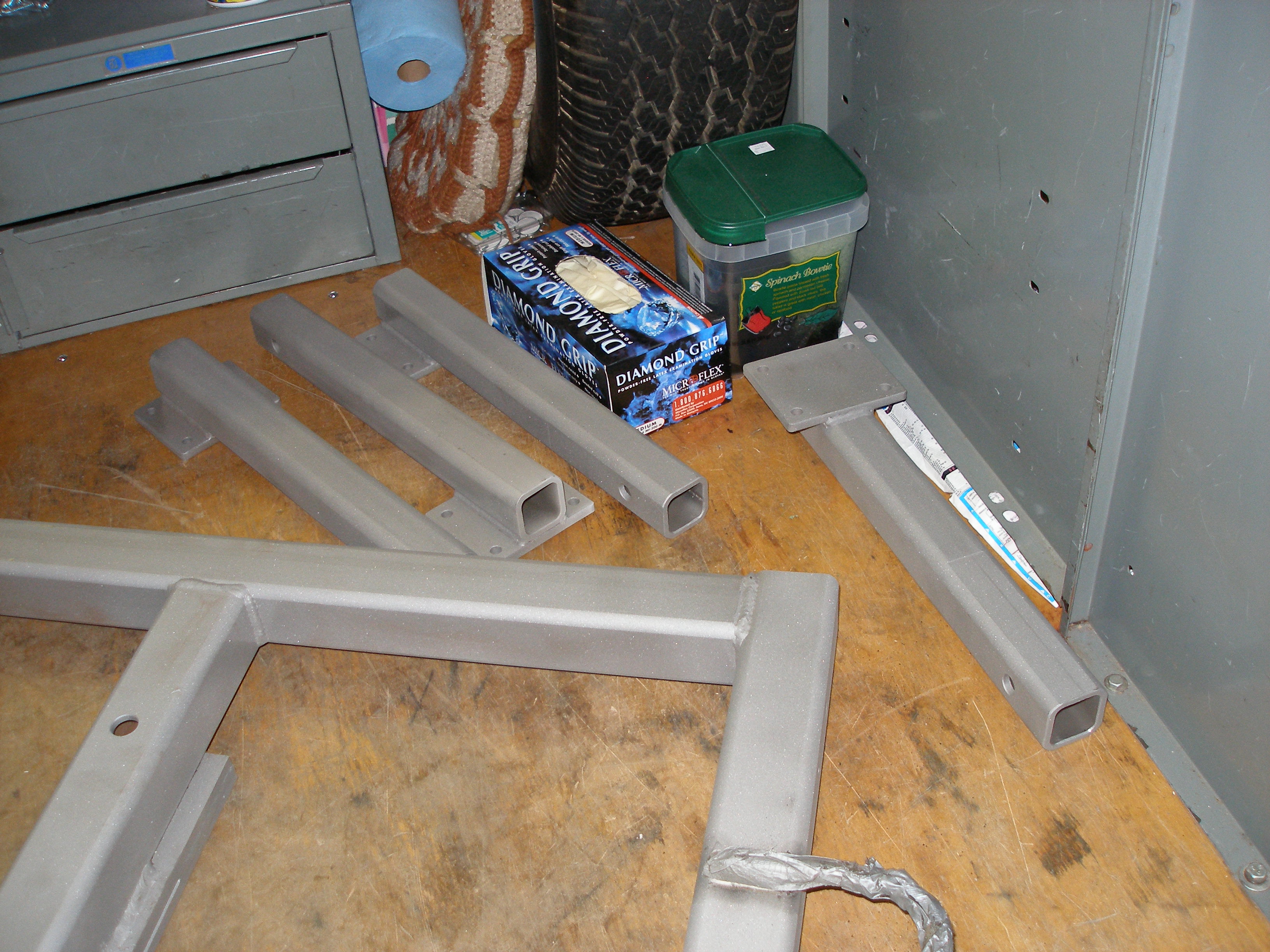
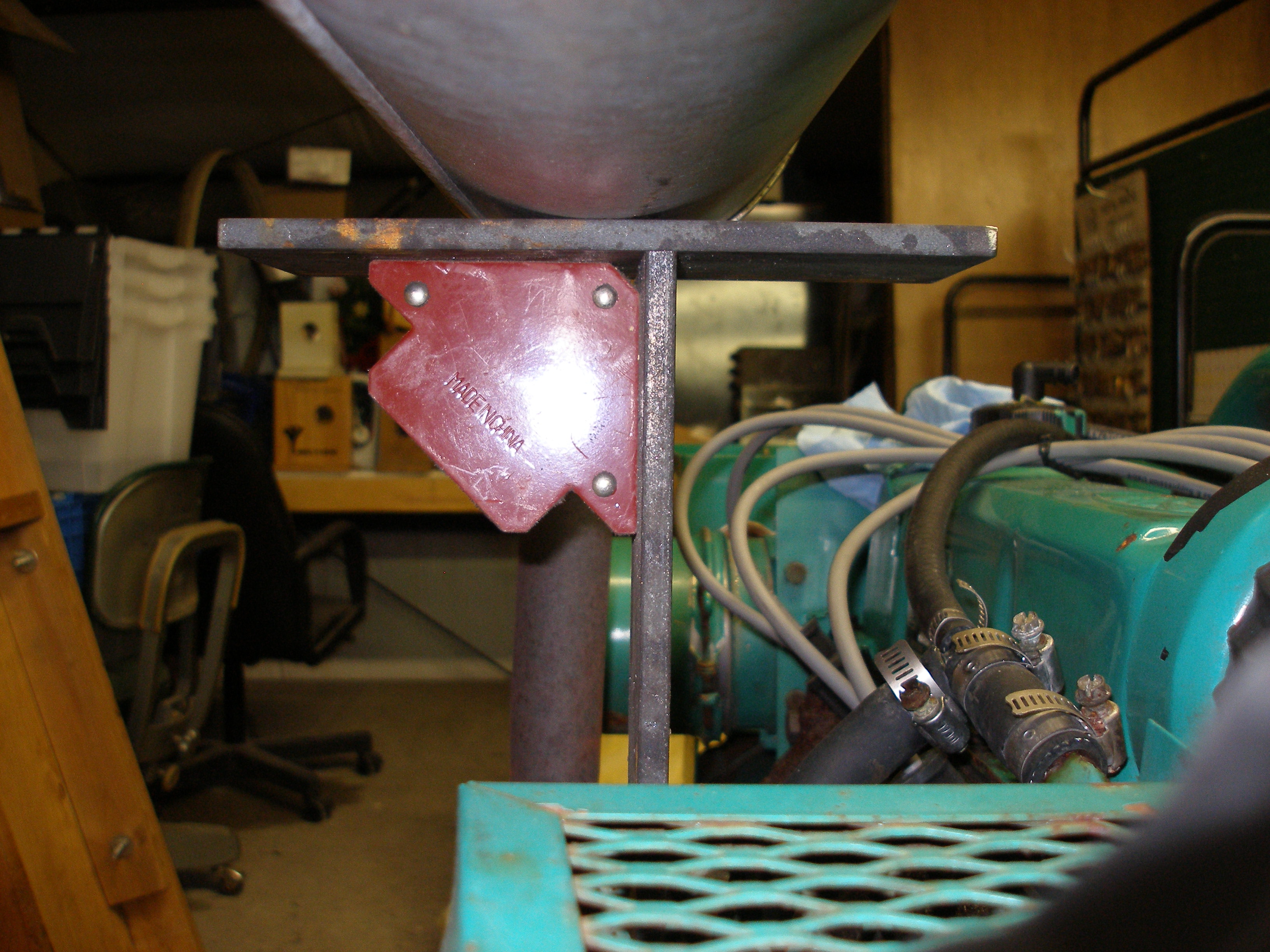
The portability frame Dad wants needs to be able to allow it to be rolled out of the garage, and in the eventuality of needing to transport it to a repair facility, to allow it to be winched on to a utility trailer (which is 52" maximum width between the wheel wells). But this genset is large/heavy enough that it's designed to be bolted down. As a compromise, I am putting a frame under it that can sit on cribbing for normal operation, but can have wheels attached for transport.
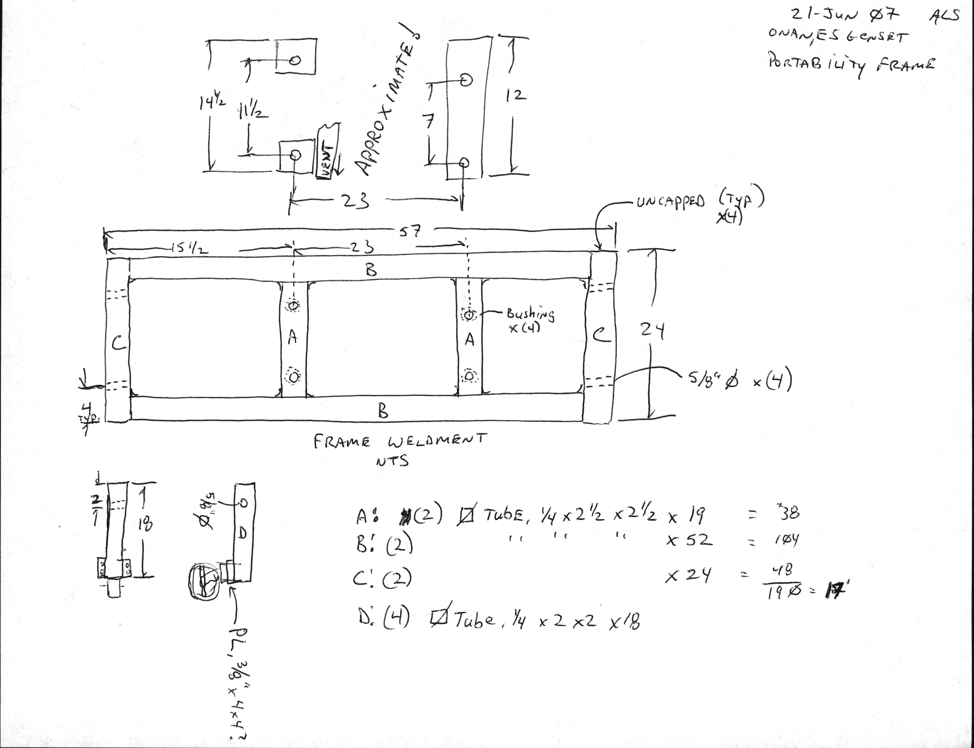
The idea is that the wheels can be removed when the frame is cribbed, to avoid tripping on them, and to reduce the generator's idle footprint (the amount of room it consumes when not being actively used). To that end, the frame is constructed such that the wheel outriggers slide into the frame in the same fashion as a typical Class III+ receiver hitch.
Over the past couple of weeks a few changes have crept in. The motor mounts holes will not be bushed -- not needed with 1/4" wall tubing, and fiendishly difficult to execute with the available resources. One SS hook loop added to each end, giving a nice place to attach a winch hook or come-along or strap (too low for a tie-down though). Outrigger through-holes are now 1/2" in outer tubes, 5/8" in outriggers (easier alignment when trying to get the pins in) and there are 1/4" G8 through bolts at the 6-1/16" mark inboard from the frame ends, so when an outrigger is slid home, it stops with the holes aligned (within 1/8", which is plenty close enough). How many times have you wished for a similar stop for your ball mount on your receiver hitch? I know I have, and I got rid of that annoying "slide in a little, slide out a little" problem using these stop bolts.
20' stick of 2.5"x2.5"x.25" wall square tubing, borrowed DeWalt chop saw from next door neighbor:
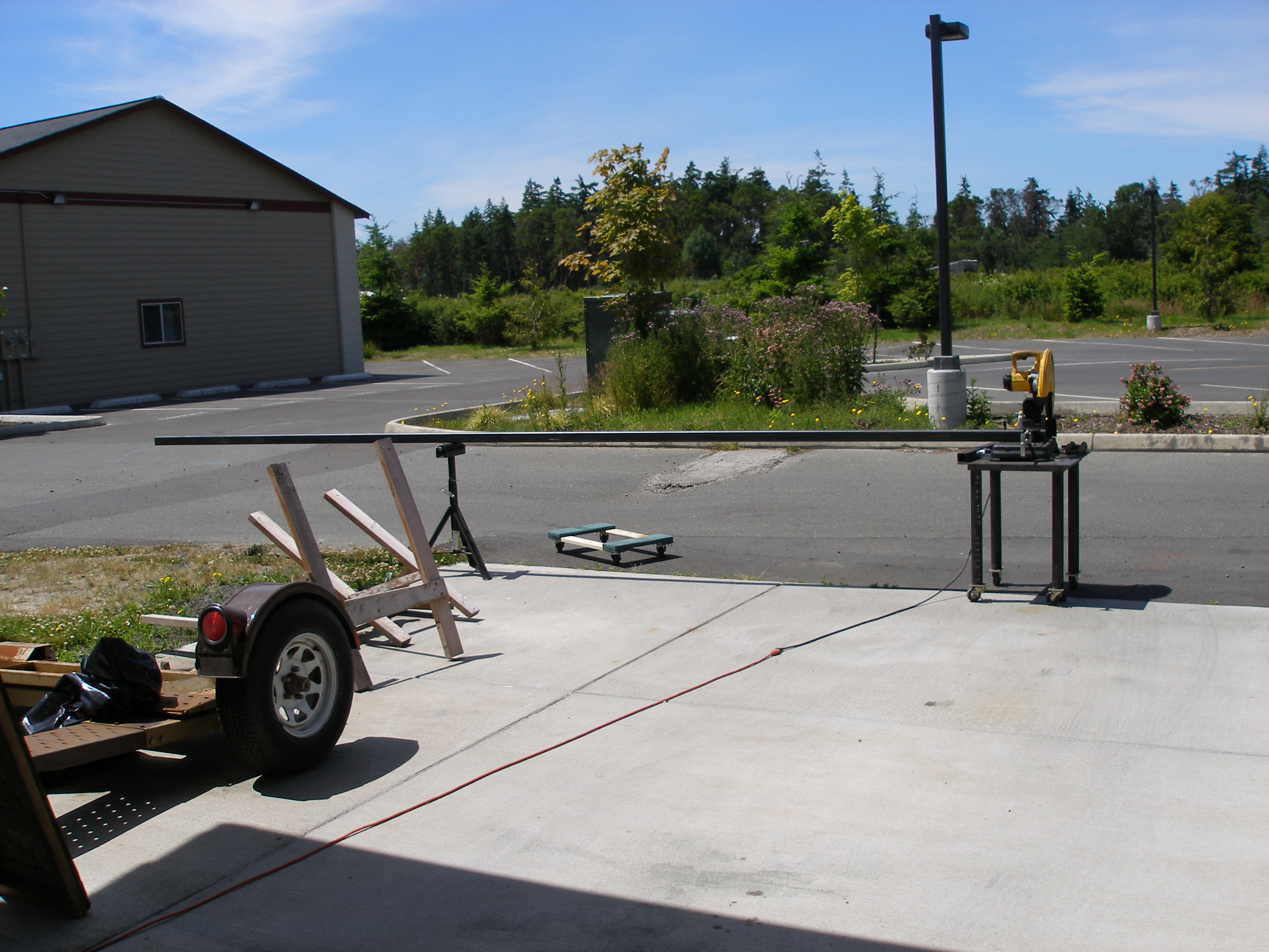
A while later . . .

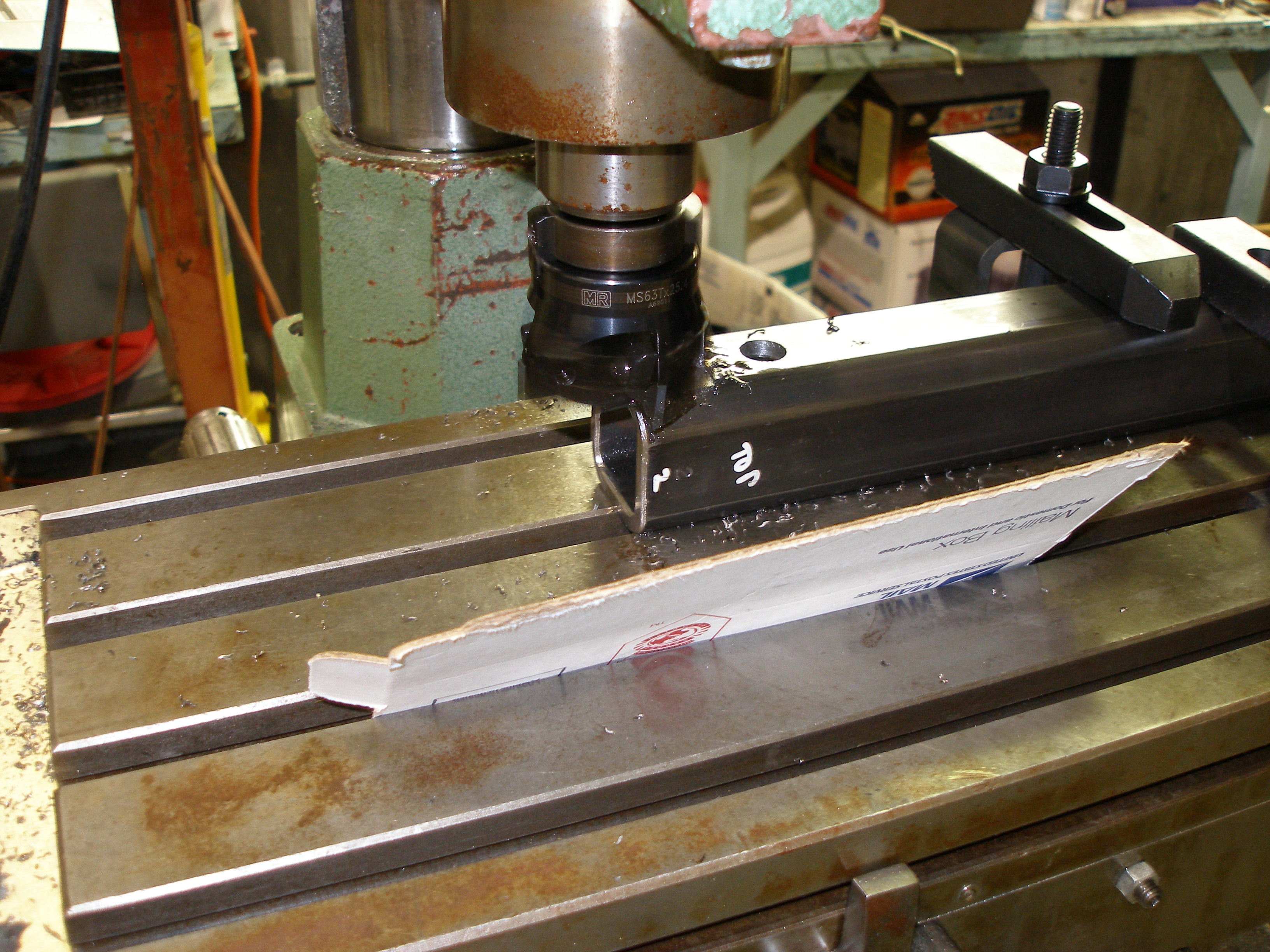
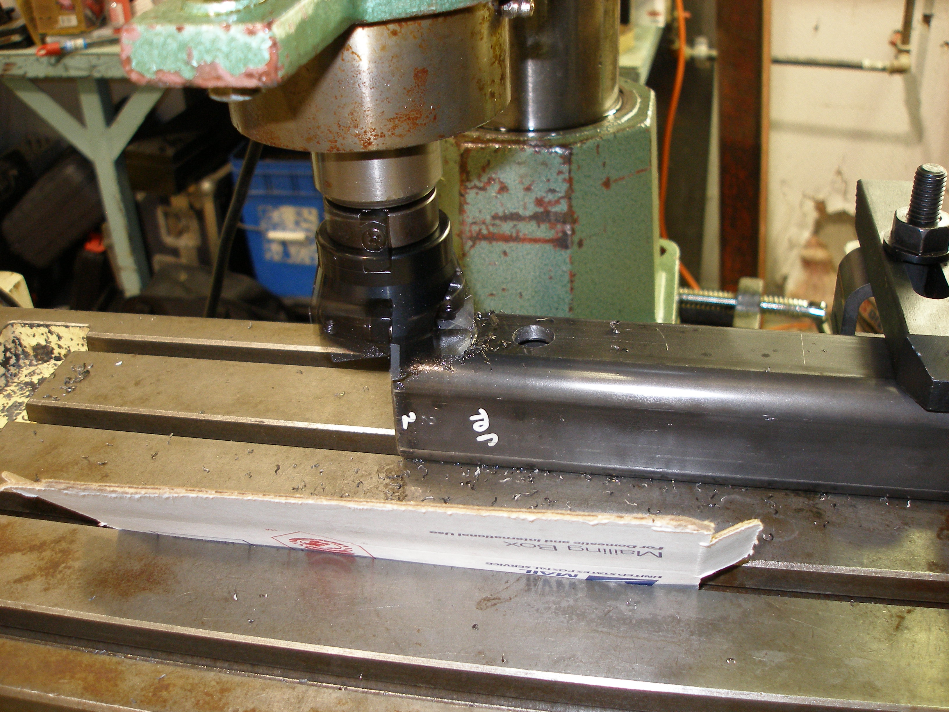
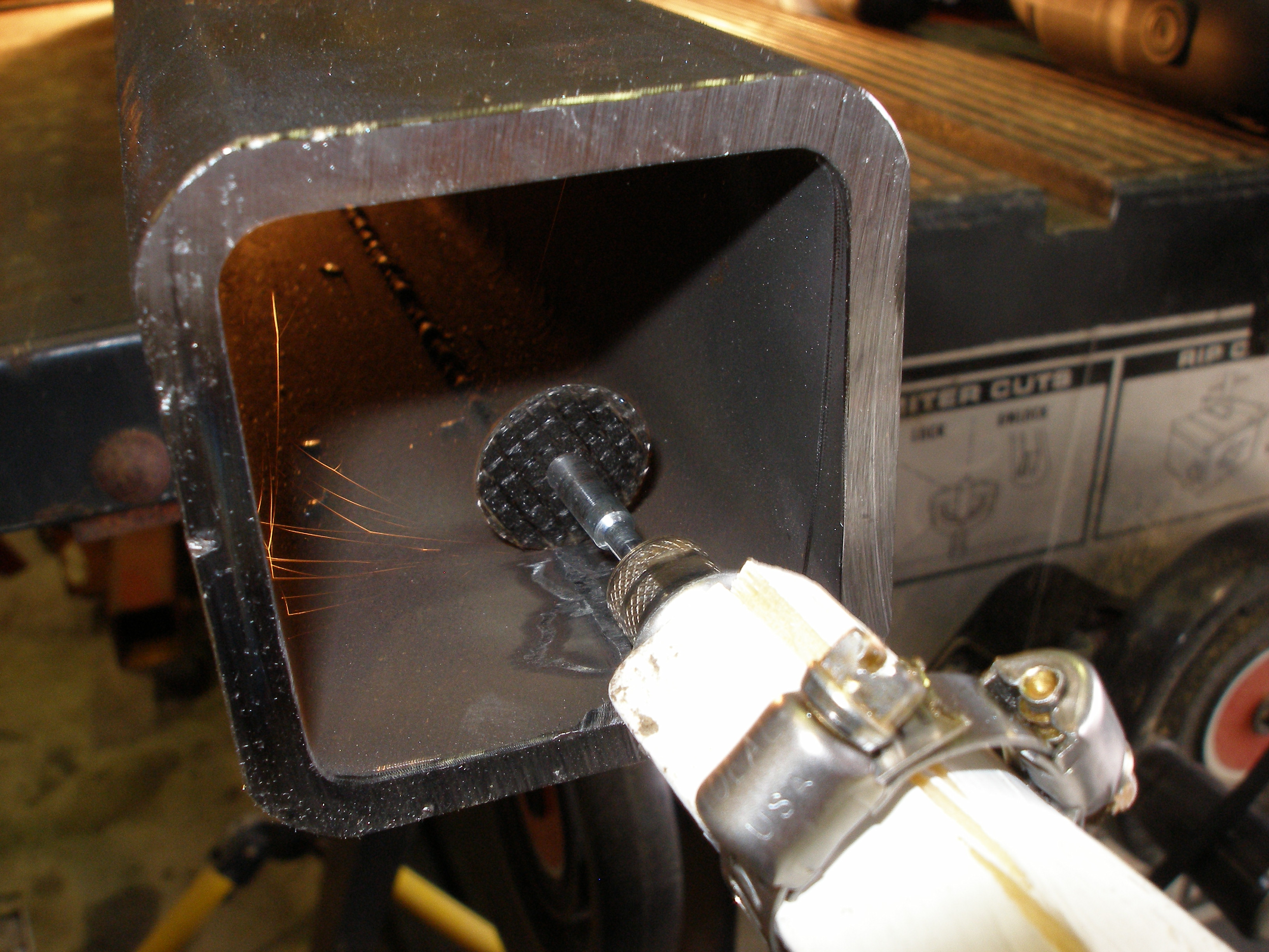
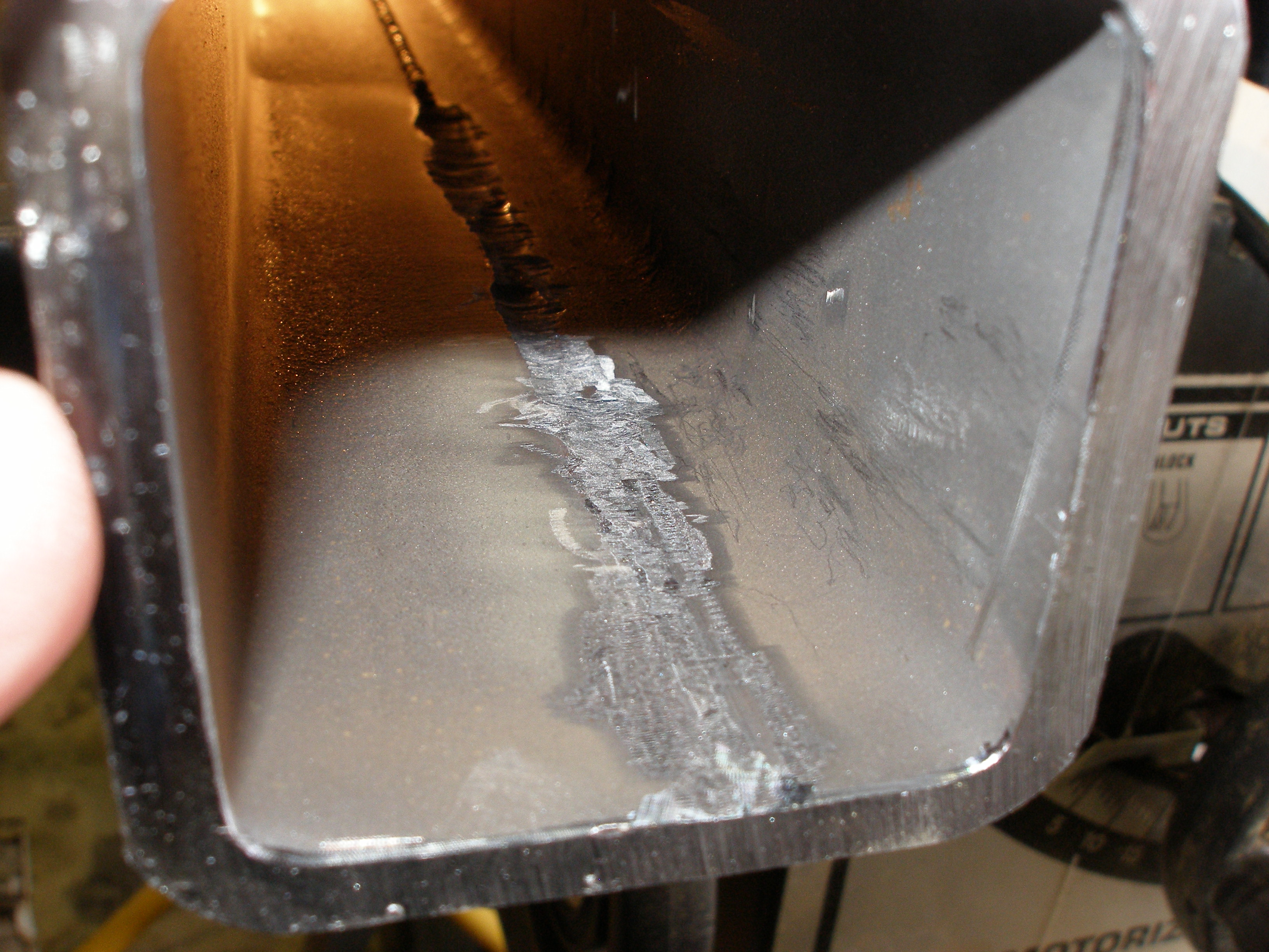
One problem right away: the tubing has a seam weld, with considerable flashing inside, about 1/8" proud of the plane. This won't allow the outriggers to slide inside the frame.
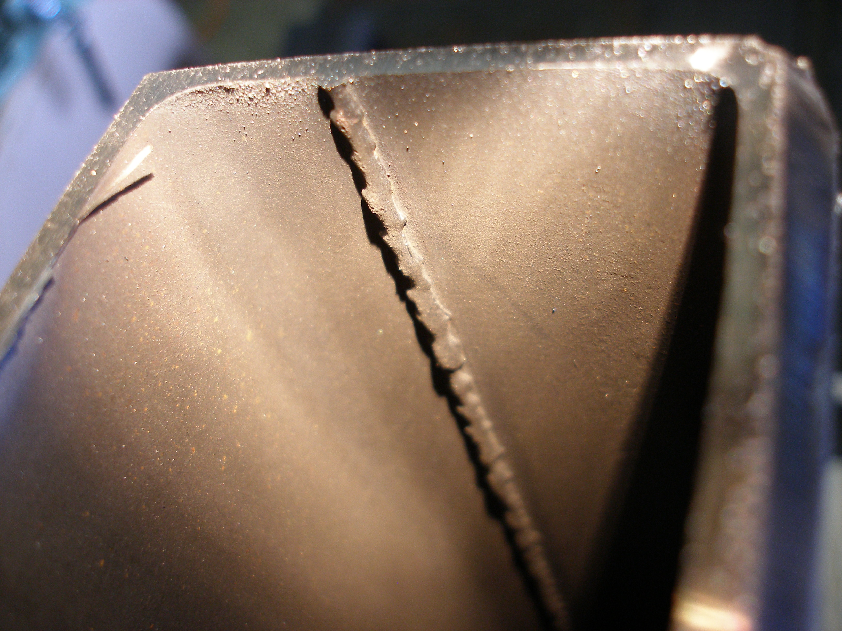
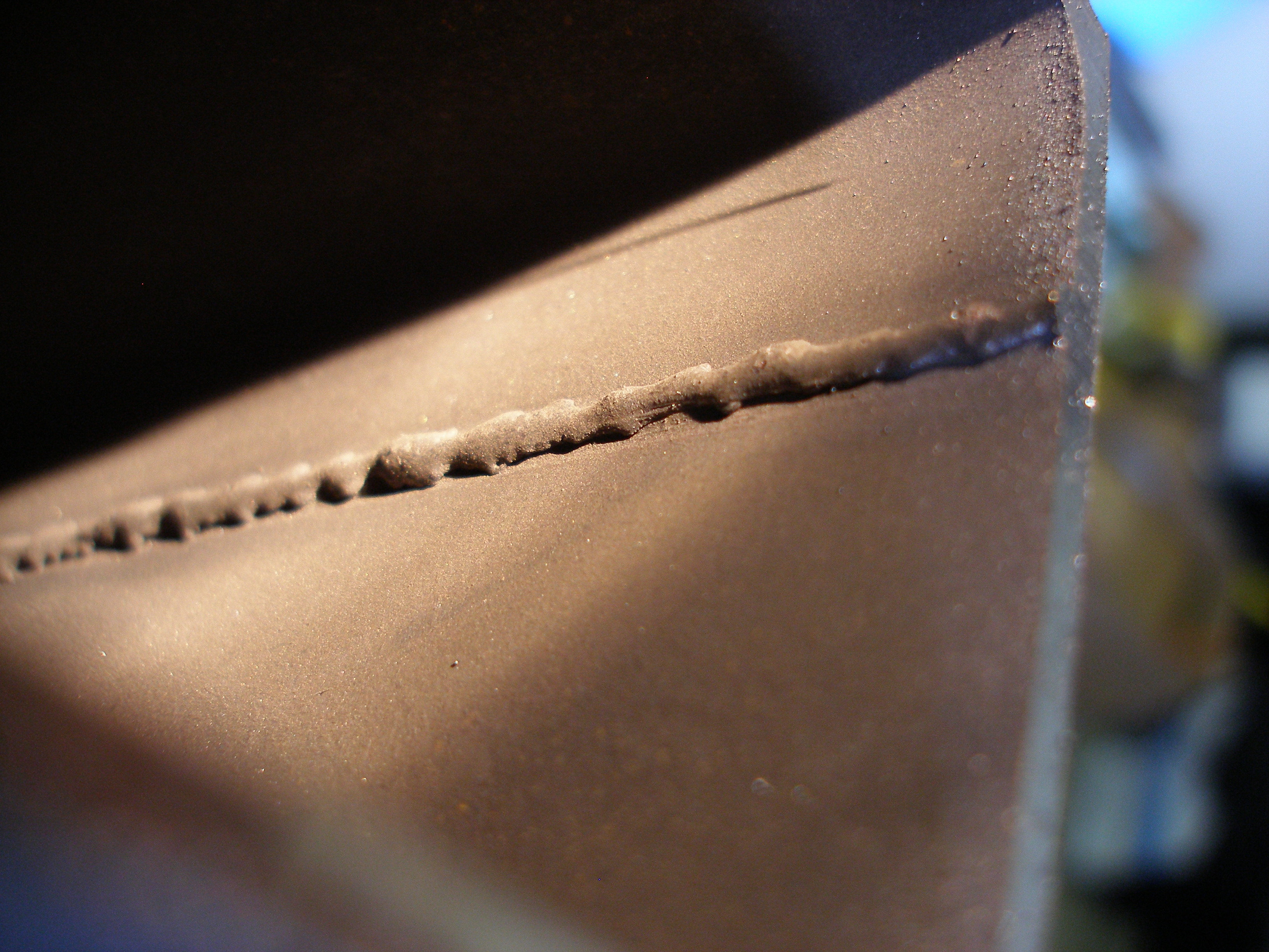
It has to go. I need better than 6" of this removed. How to do that? A good deal of thought expended, then existing resources marshaled:
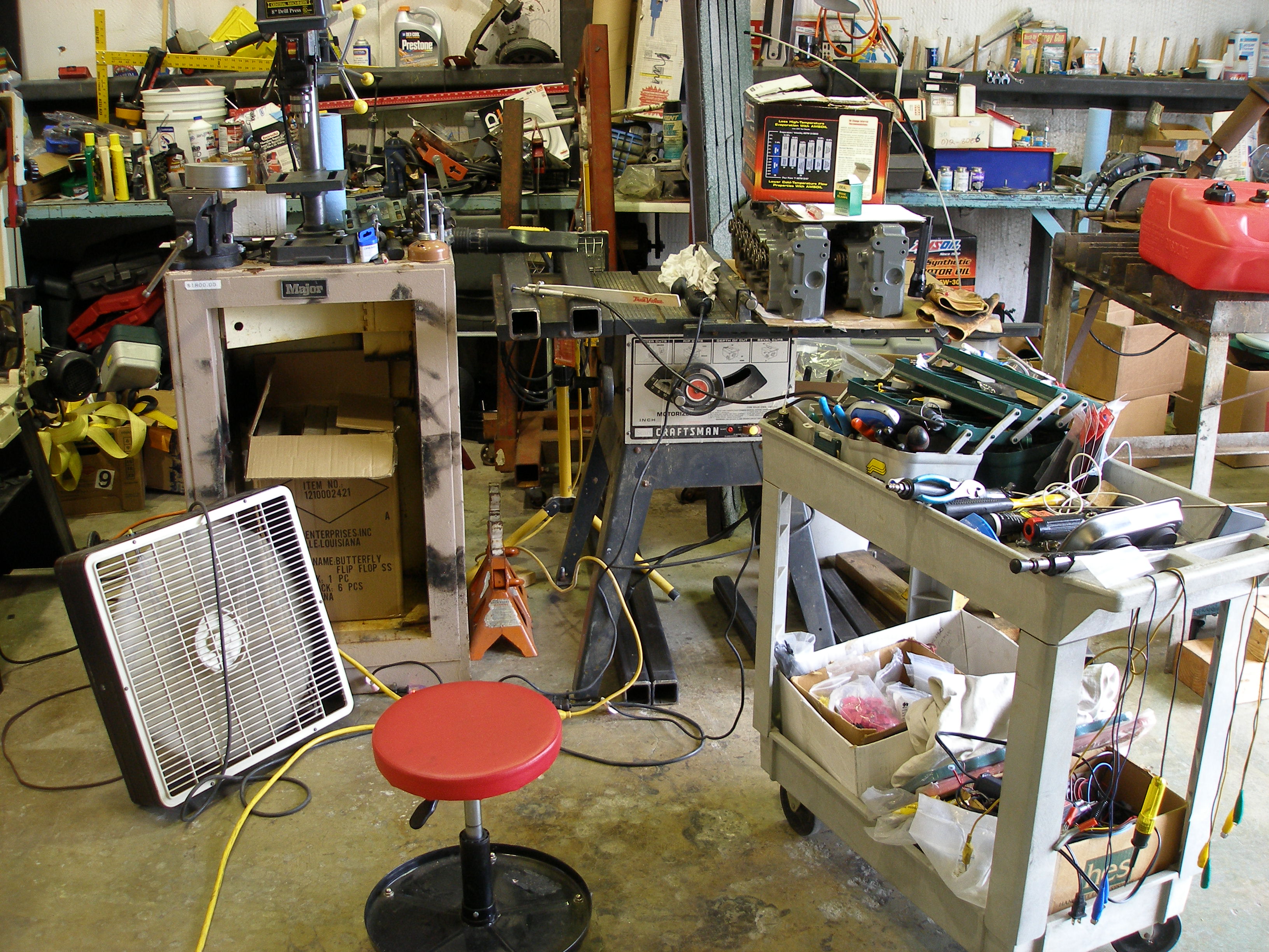
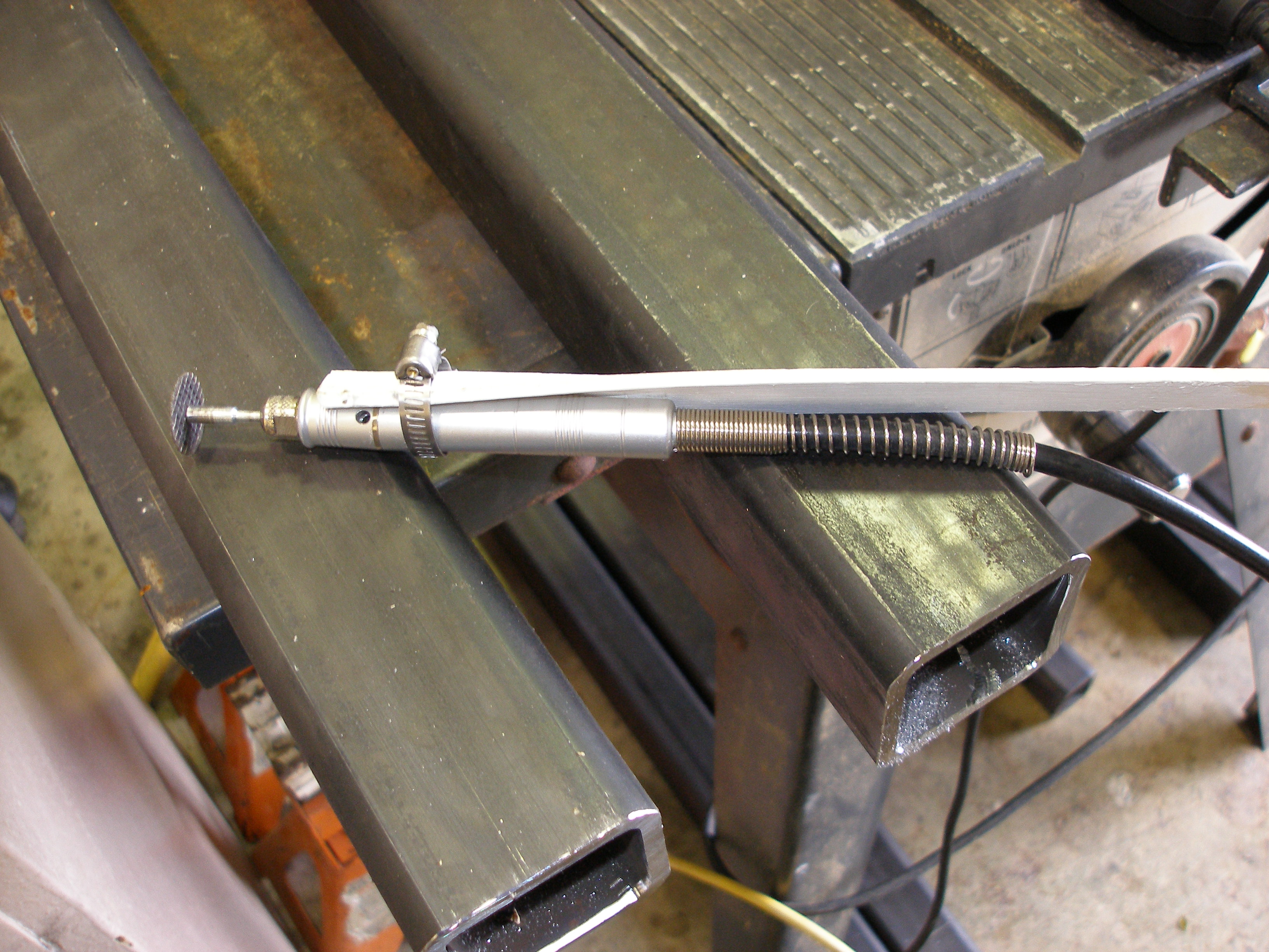
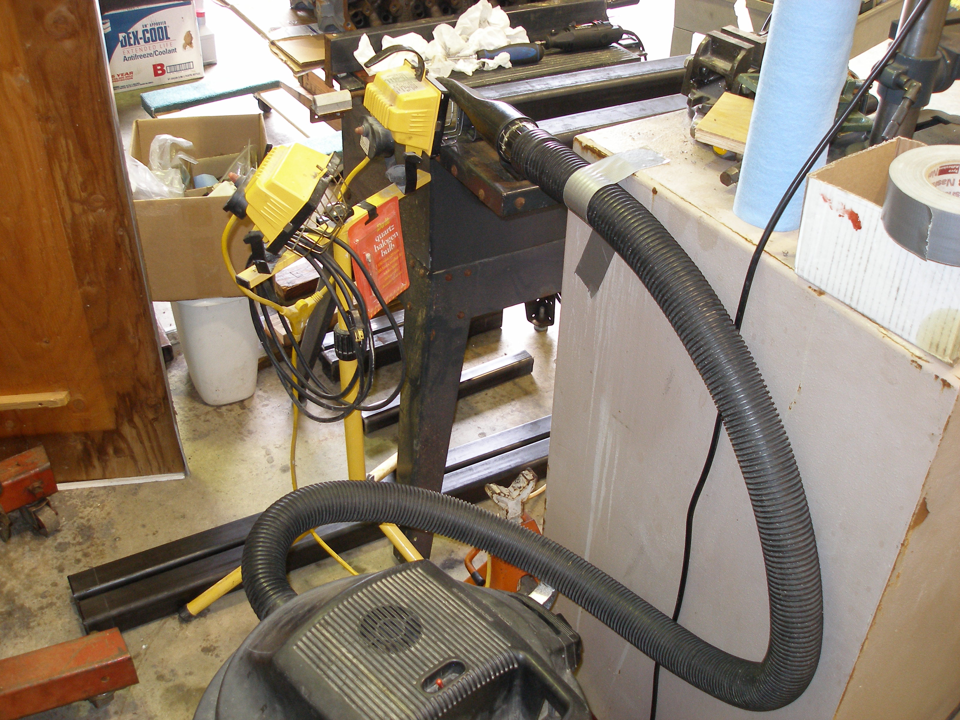
This requires some explanation, as there's a lot going on in these pictures.
The flex-shaft Dremel (one of three Dremels I own) has the usual No. 402 mandrel and 426 Reinforced Cutoff Wheel. Extending the reach is a True Value paint stir stick, to allow 7" reach inside the tubing. The table saw is the work surface prop. There is a yellow worklight tripod behind the tube being worked on, shining light toward my end. The shop vac's nozzle is taped to the halogen light's shield to provide some airflow away from me and the cutoff wheel -- absolutely critical to success. The Rubbermaid tool cart is holding up the Dremel to reduce the amount that the flex shaft has to work. The box fan is keeping me cool in the ambient 80° heat, while I'm sitting on the red Harbor Freight rolling stool. The grey V8 heads are the spare rebuilt 6.9l Ford/IH diesel heads that I'm trying to sell, and they provide work surface ballast, because those square tubes are heavy. Not shown is the bit of cardboard that shields the halogen lamp from me, it lays outside the tube so only light inside the tube reaches my end.
A flashlight was still needed for the last couple of inches in each tube.
To do 7" x (4) required about an hour and a half. I had to do it twice -- the first time, I'd done the wrong crossmembers! So I got lots of practice. Took about one cutoff wheel per 6" (ie I used ten wheels total).
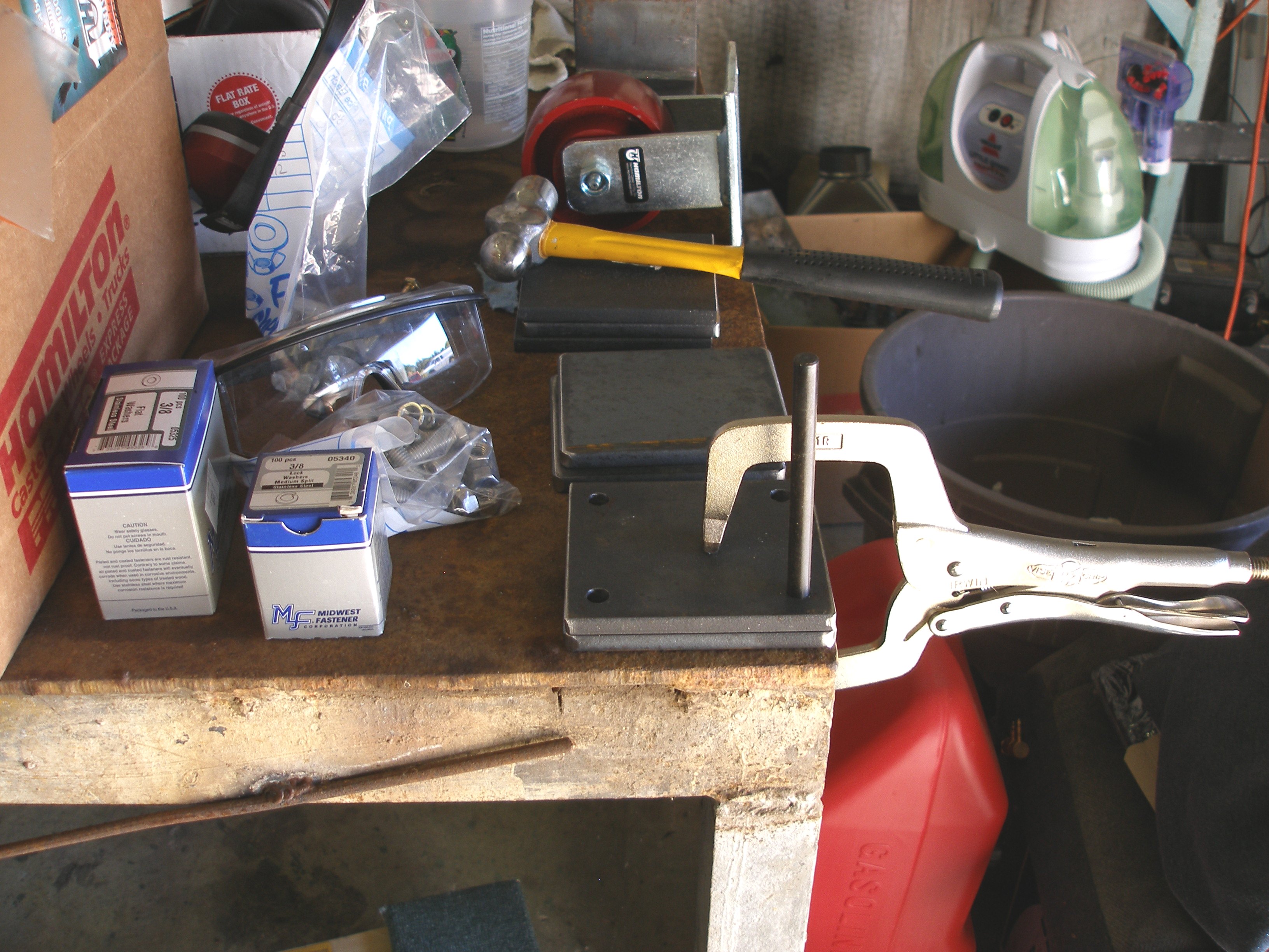
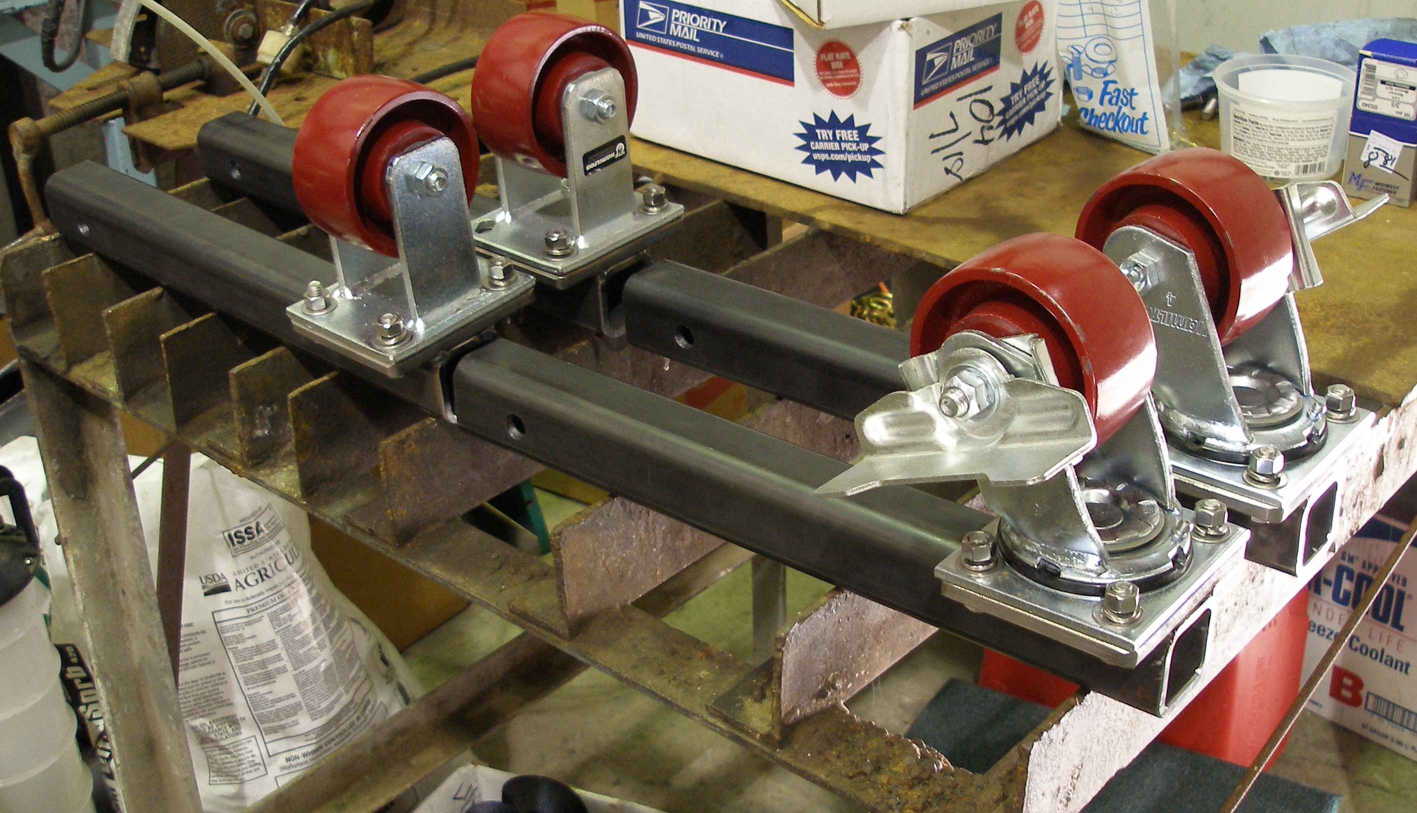
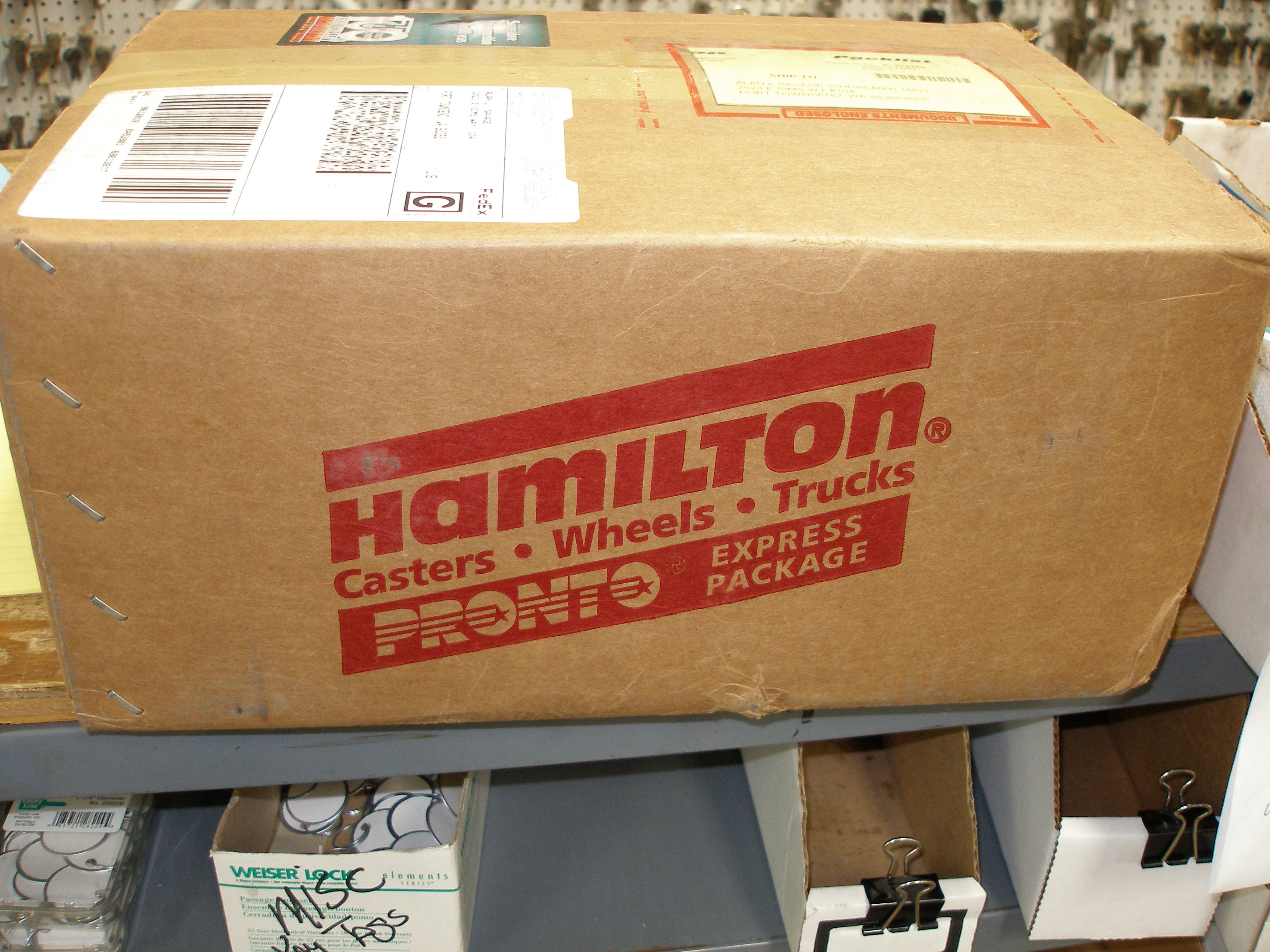
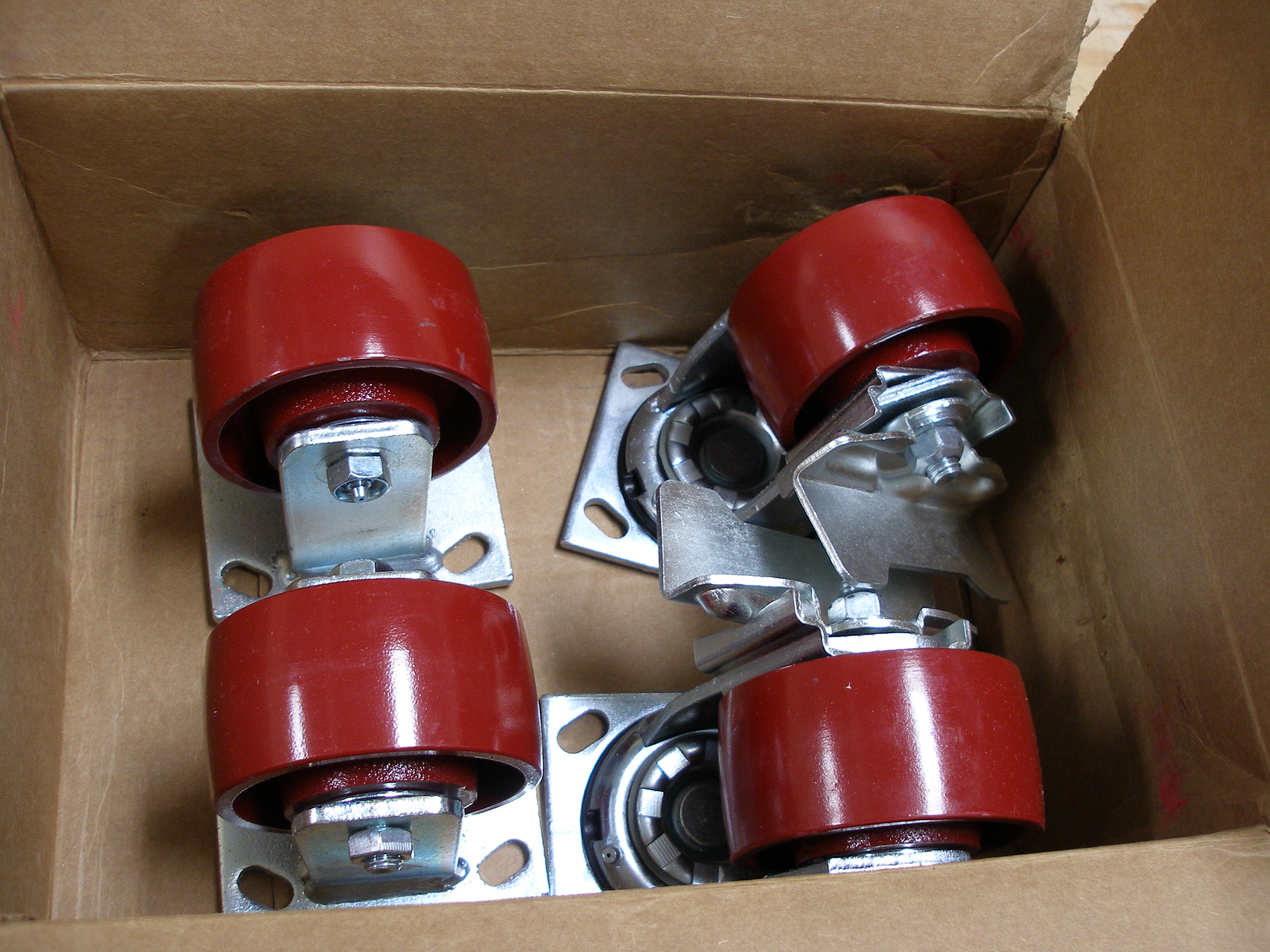
Casters are Hamilton. They've been making casters for 100 years.
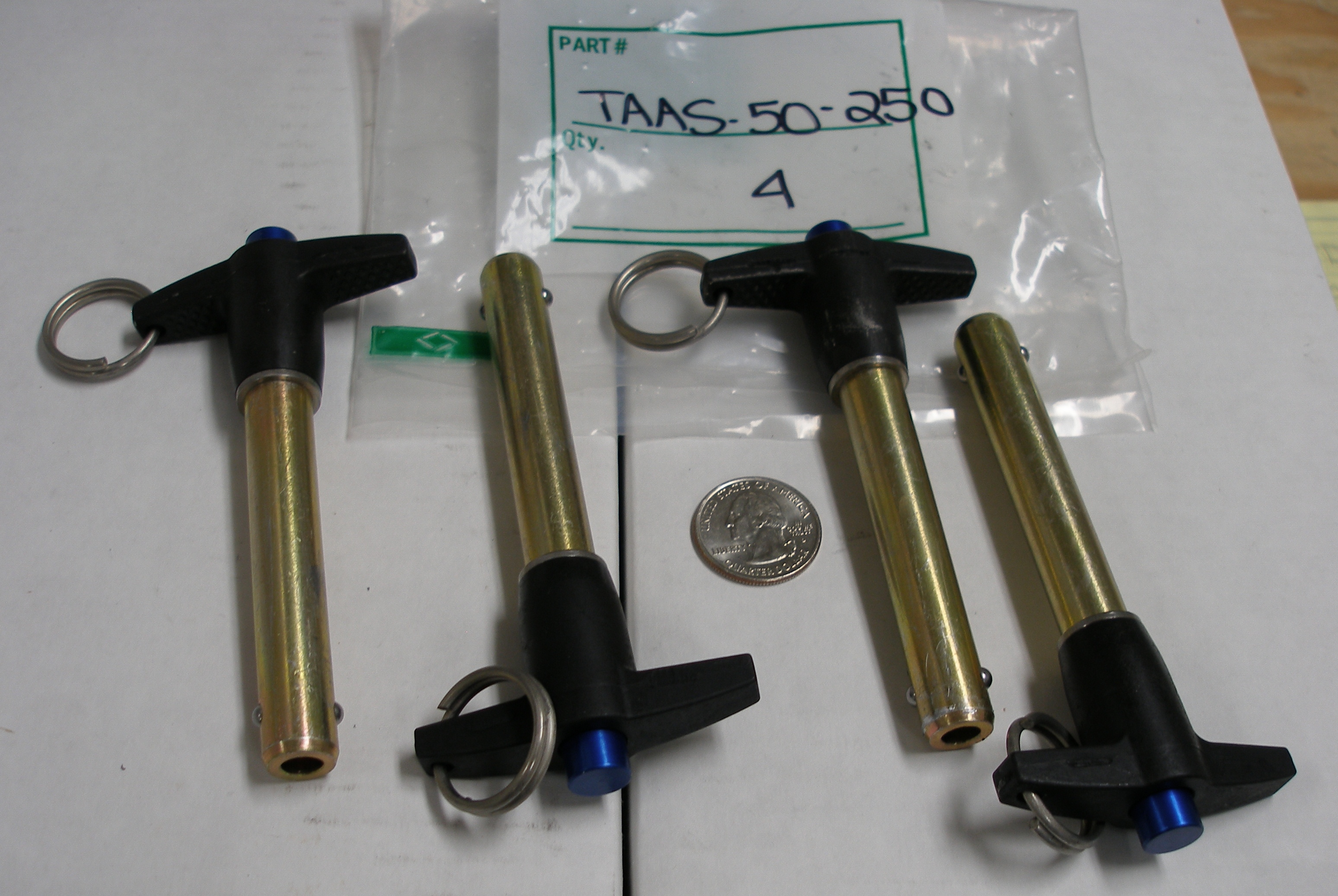
These are the quick-release pins for the outrigger wheels. Very nice units.
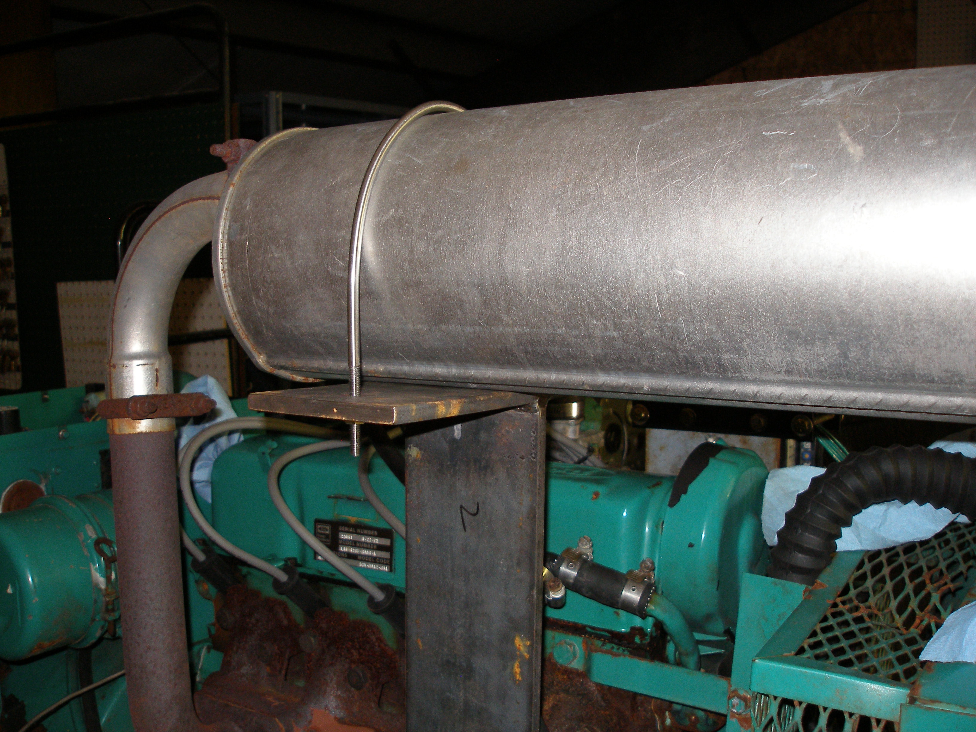
The muffler is overshadowing the area where the wiring receptacle will be, and the muffler is cantilevered on the exhaust manifold: bad.
I swiveled the muffler to point out the front (the fan is a pusher so the exhaust now moves the same direction as the cooling airflow).
Now for a support:
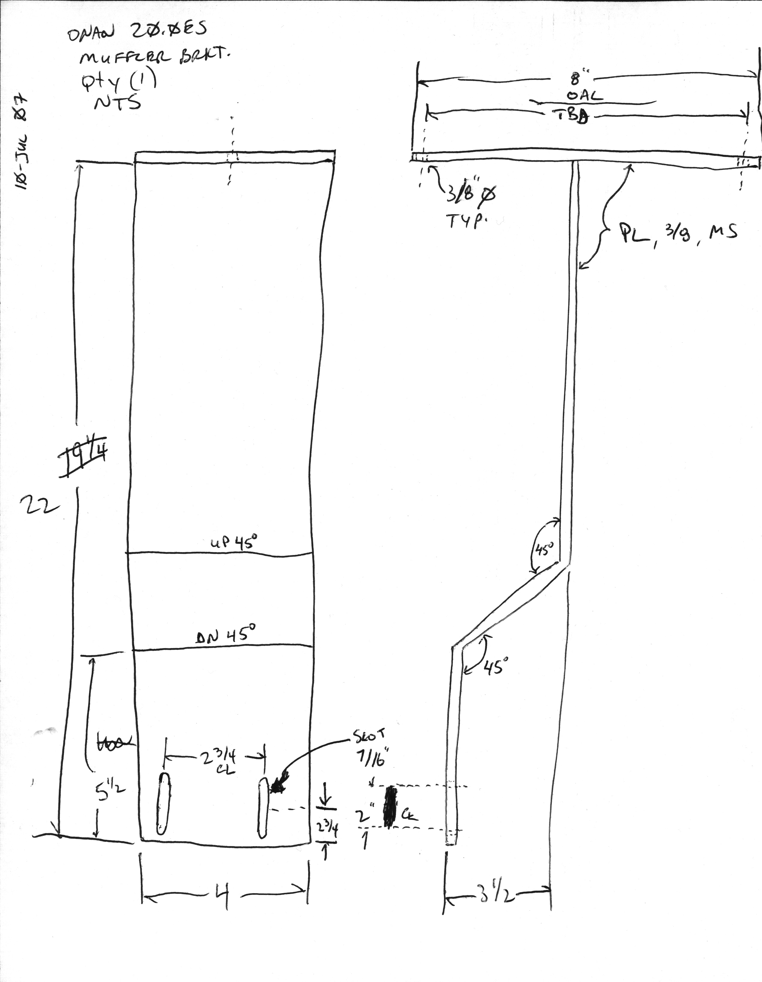


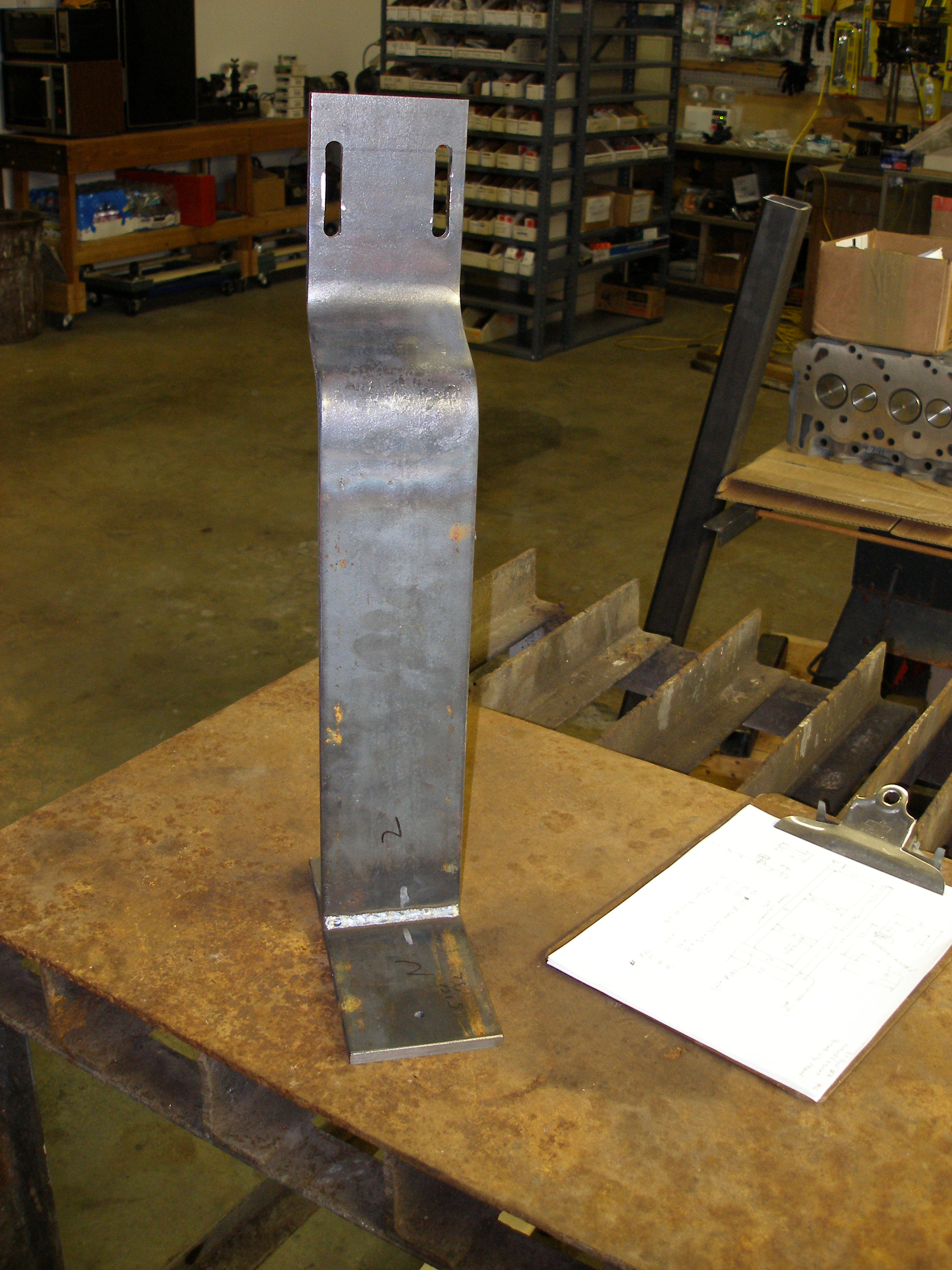
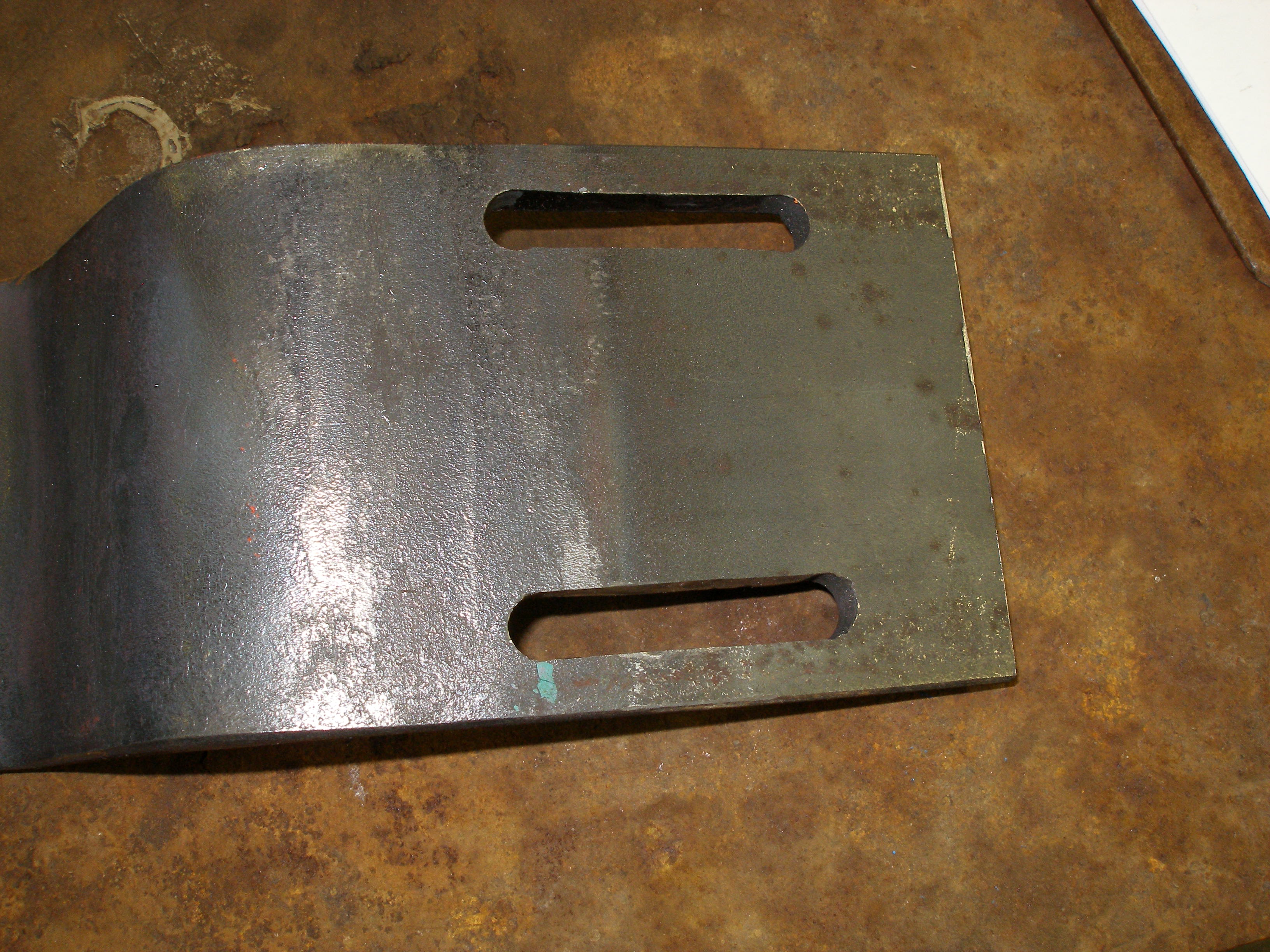
Making those slots in 3/8" PL with a Dremel takes a loooong time. But I have no milling machine available and I'll be damned if I'll pay the machine shop to do it.
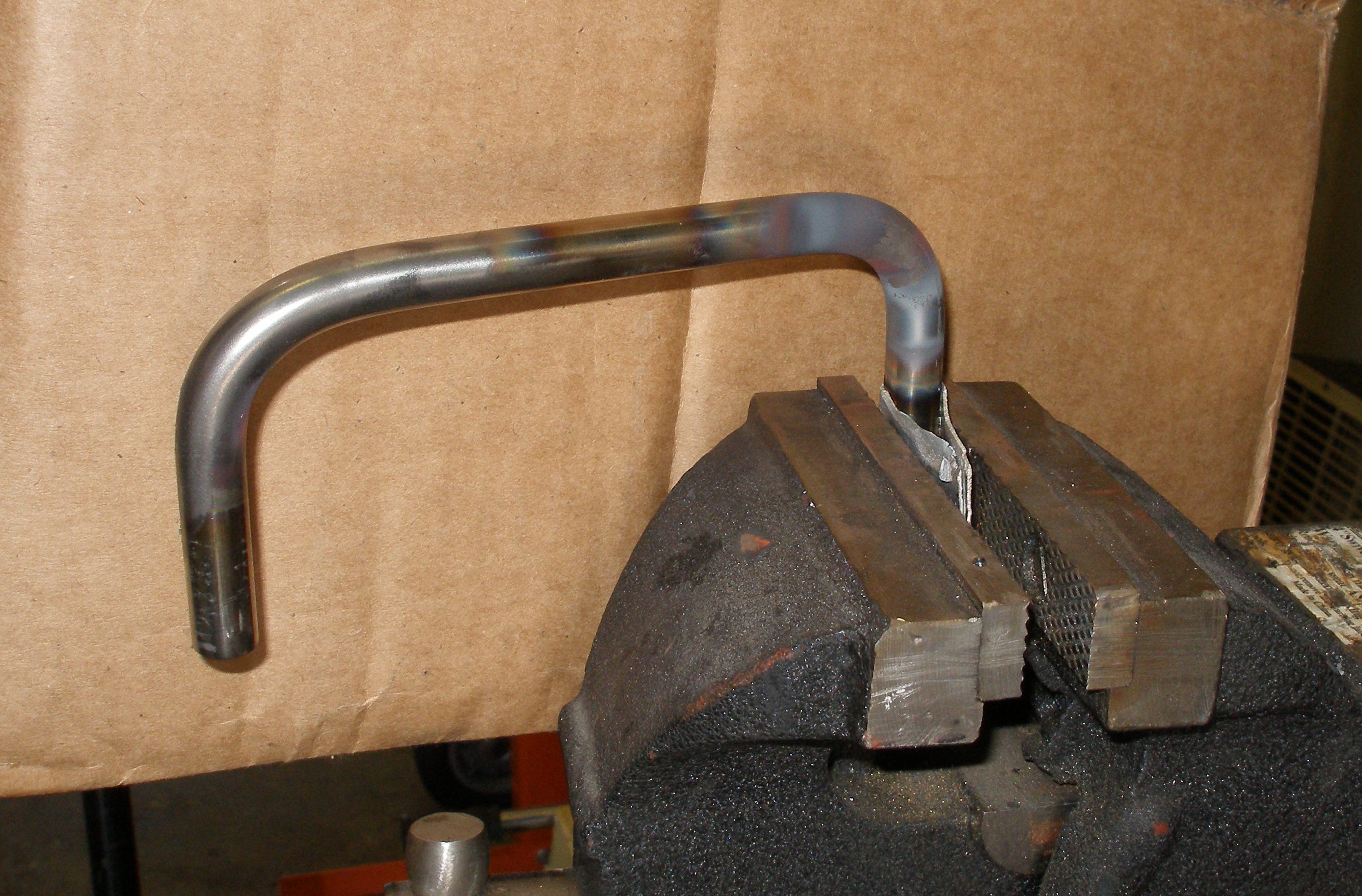
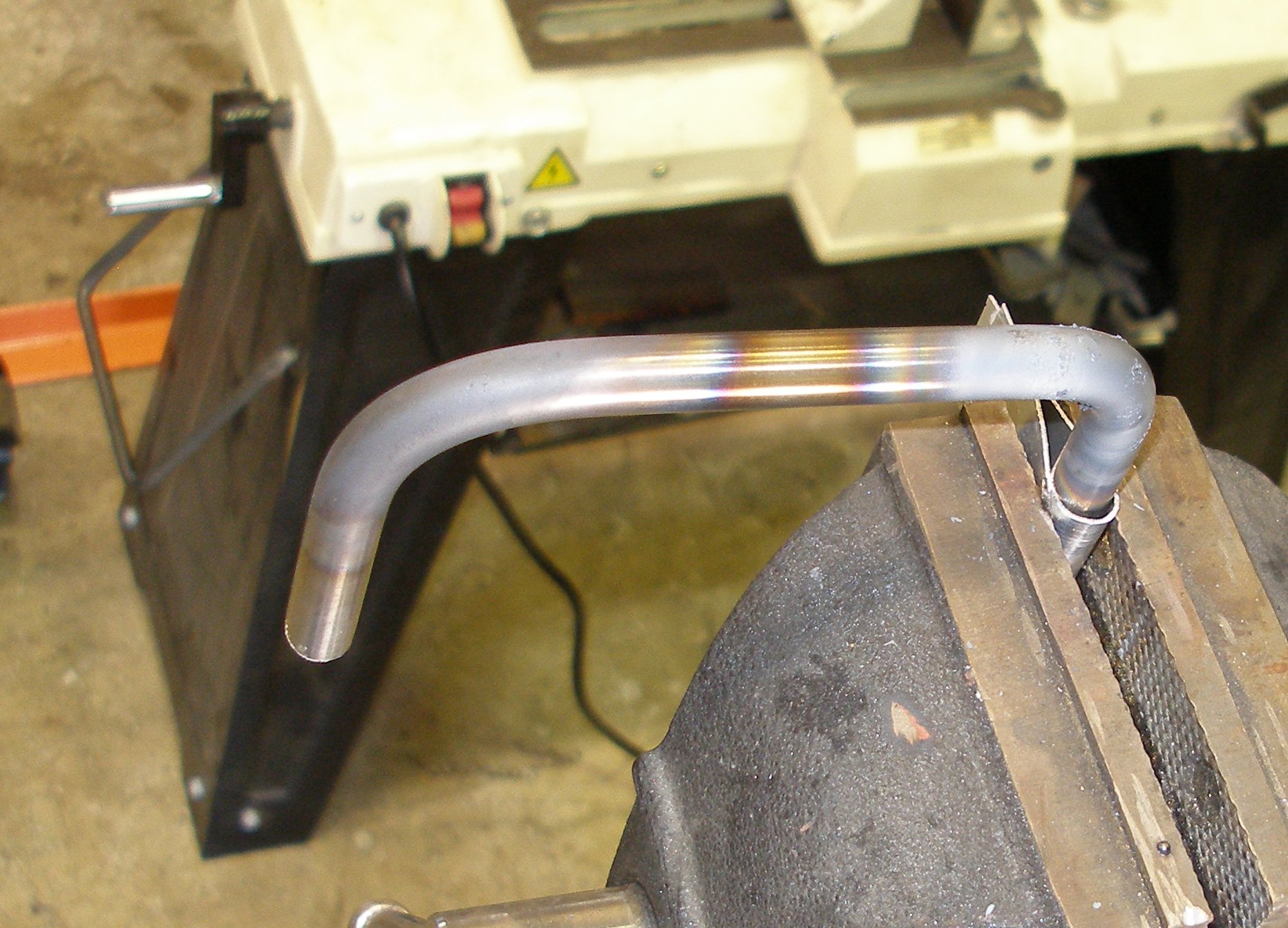
The muffler will have some 1/4" RB formed in a U and bolted to that top plate. Prevents rattling and free vibration.
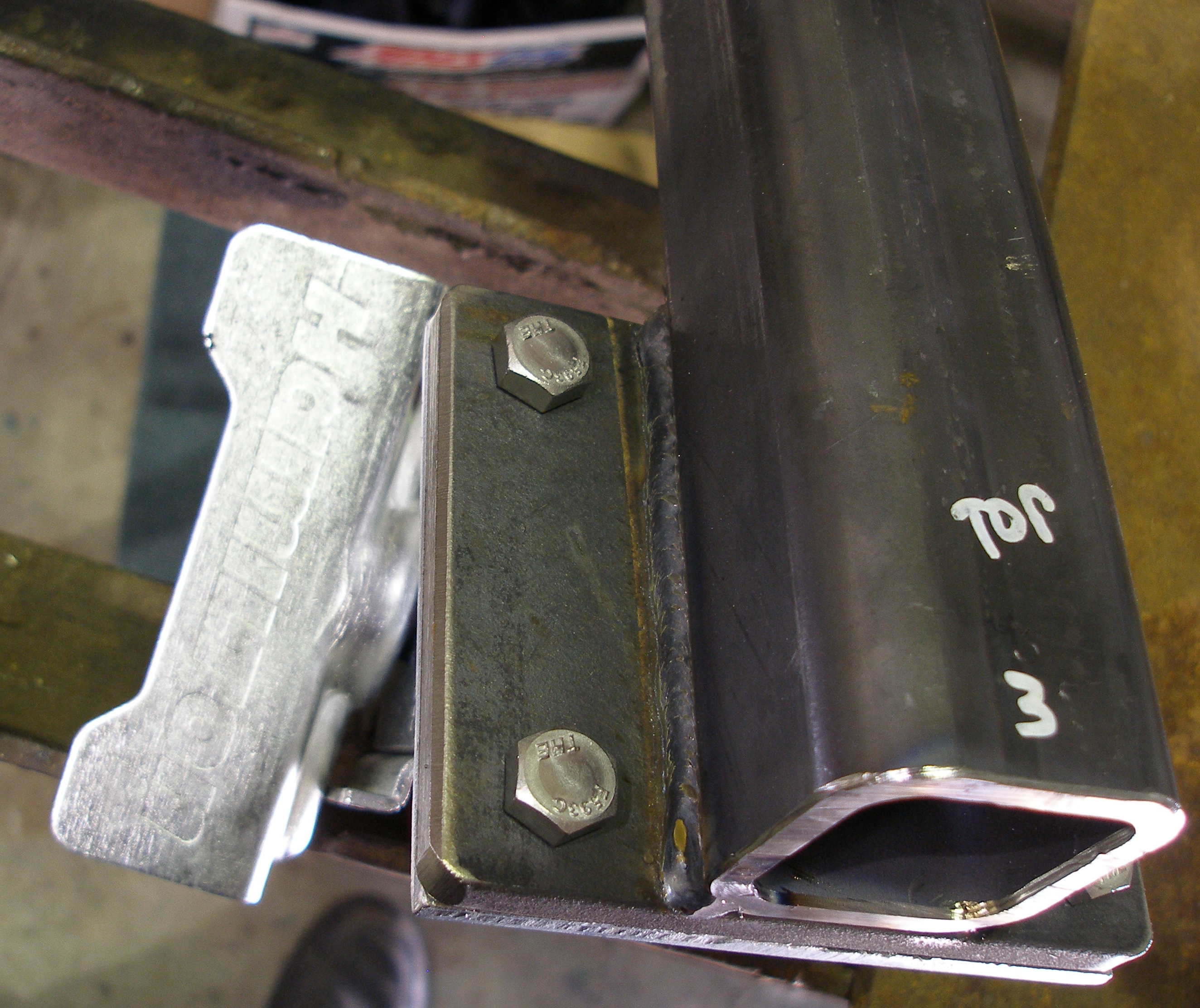
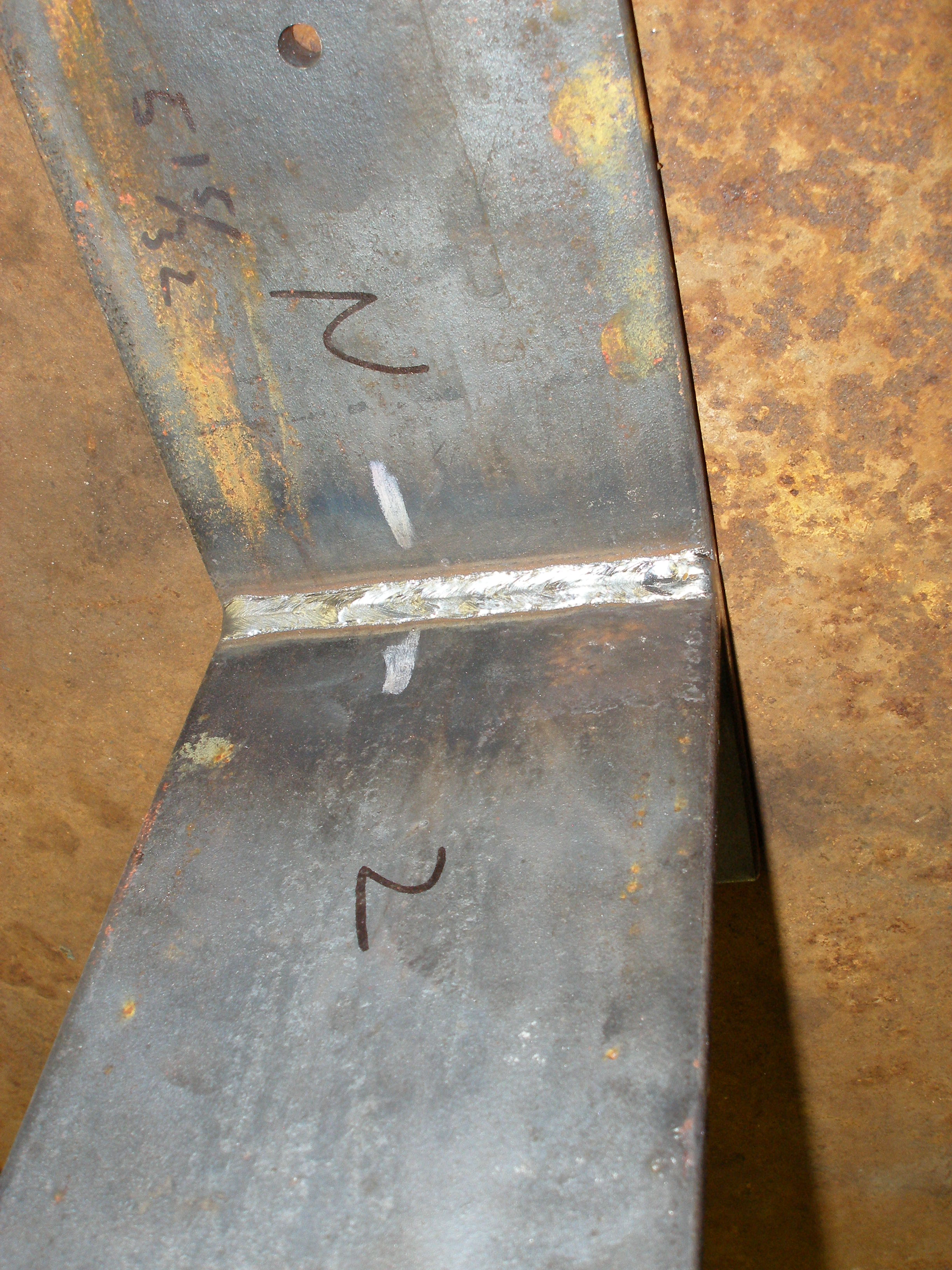
The welding of this bracket was a test for a new welder that I want to use. He passed my test
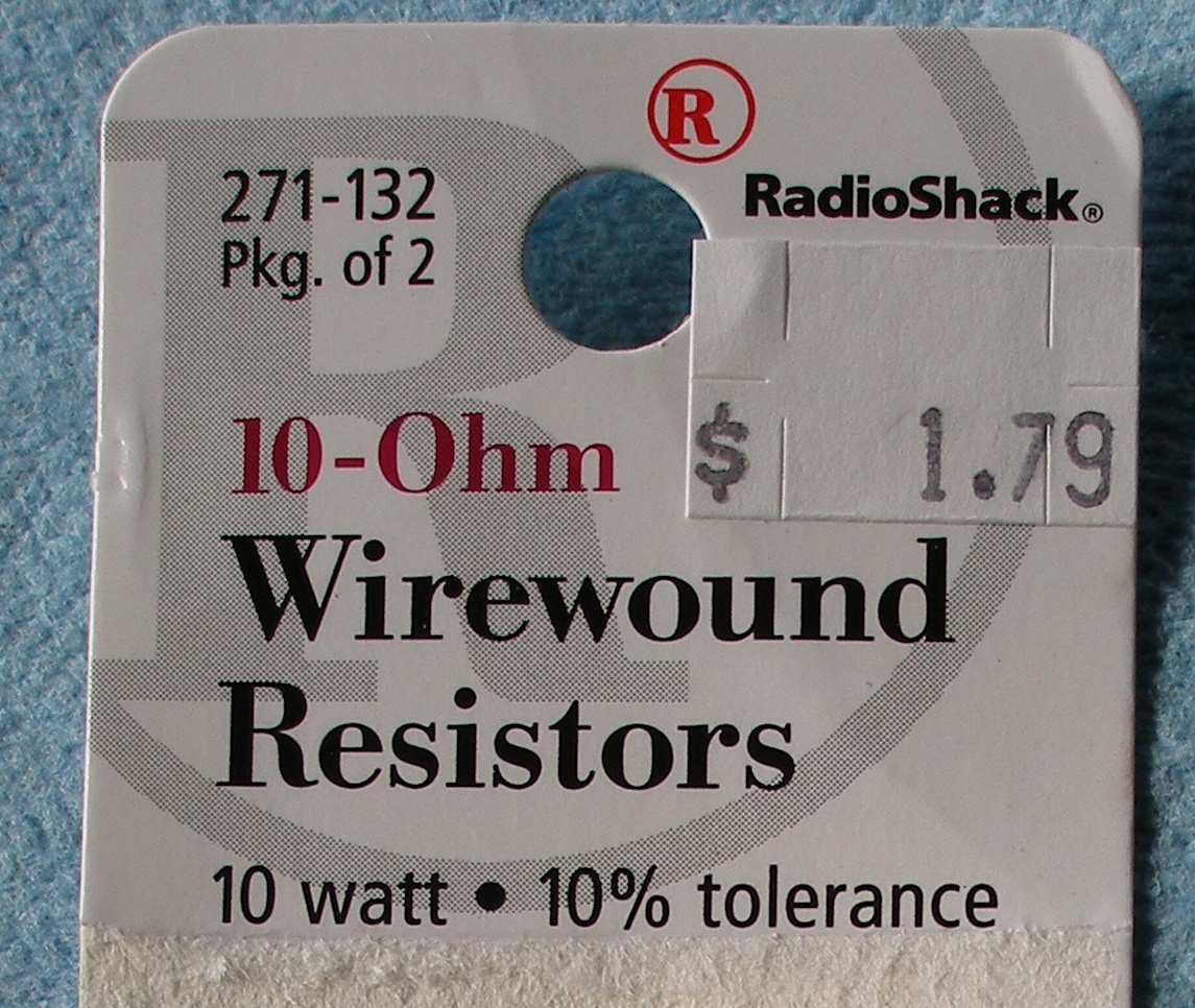
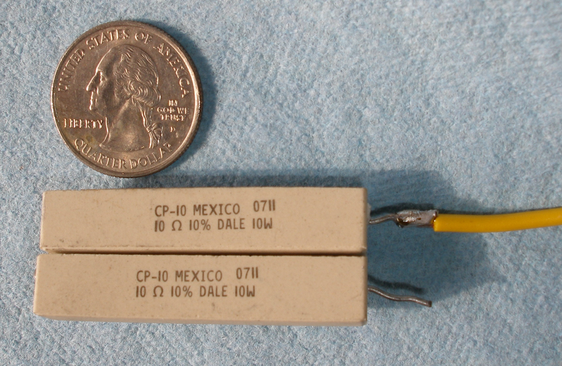
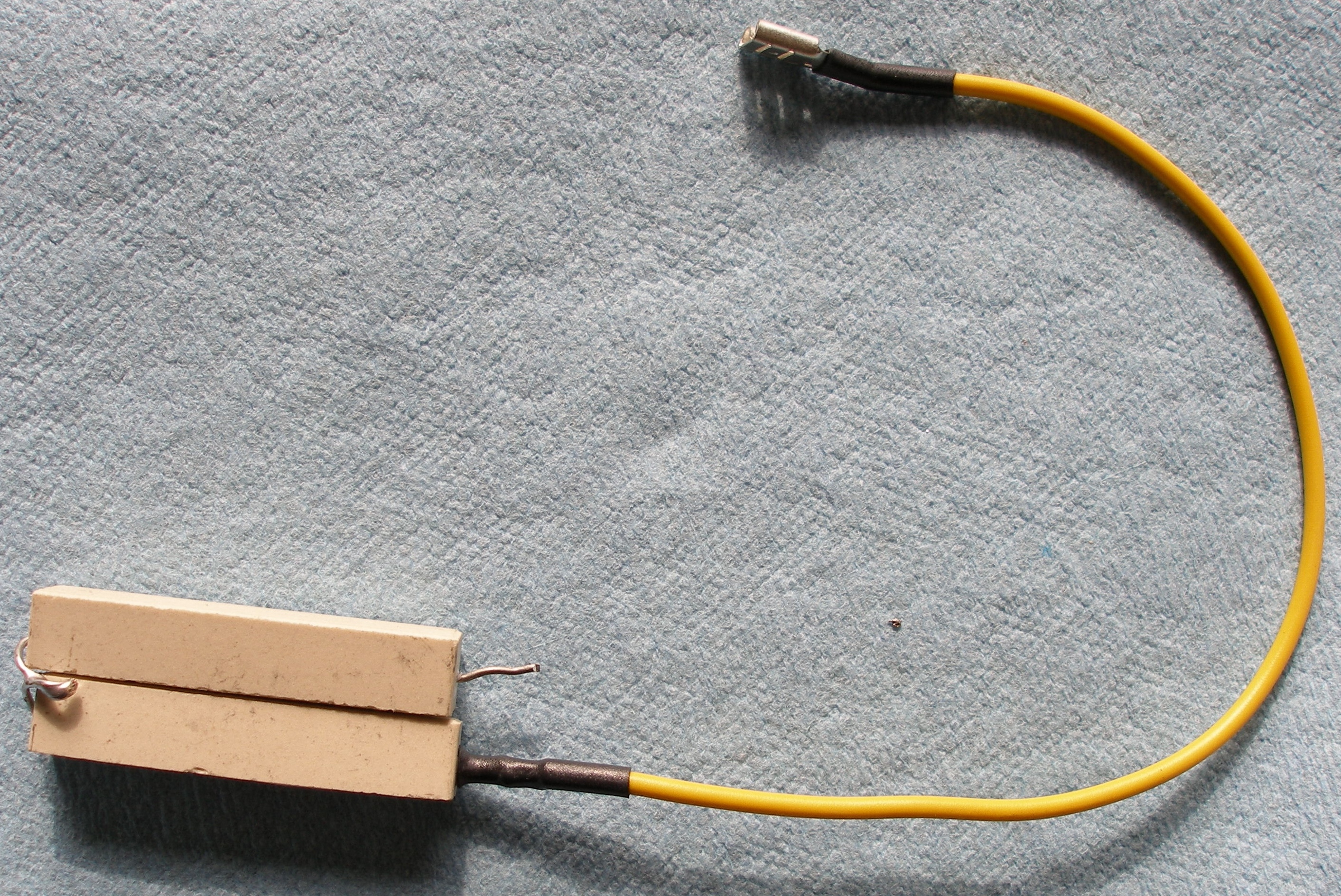
If the generator's exciter field is going to need to be flashed more than once in a looong while, the procedure has to be easier. How about a momentary-contact switch on the front panel?
That requires 20 ohms in series with the 12v supply.
Also added an ON/OFF power switch for the Woodward TQ-125 governor, to allow startup without immediately going to 1800 RPM.
More later . . .