I am trying to figure out a few things about the diesel engine swap.
I found a sensor on the timing cover housing behind the high pressure pump pulley. Im assuming that this is for a tach. I cant think another reason to have it there. Can anyone tell me how to hook it up. I beleive I have a single tach wire that use to go to the coil.
Im having fun lol trying to figure out the... for lack of a better word, ignition system. Im guessing there has to be a electric solenoid that controls the fuel in the high pressure pump? Somthing that can cut the fuel off so the engine will shut off right? I see a bundle of like 4 or 5 wires going into the top of the pump and Im assuming that those have somthing to do with though Im not sure at all why so many wires.
Timing the injection pump has me at a loss. You see there are 3 timing marks on my pump. A B and C on the outer side and AB and 00 on the inside. So Im guessing the 00 marks are for the LD28 and I should be lined up with what corresponding mark? Im not sure what happened but I havent yet located any marks on the crank side pulley.
I have a few more problems to work out before it runs. I plan on dropping the oil pan today and checking the bottom end out before I go any farther. The engine was comp checked before I bought it but its always good to check for wear.
Ray
Gasser to Diesel swappers
Moderators: plenzen, glenlloyd, goglio704, Nissan_Ranger
-
DMS
- Posts: 117
- Joined: 17 years ago
- Location: Prunedale Ca. 93907
- Contact:
-
asavage

- Site Admin
- Posts: 5433
- Joined: 18 years ago
- Location: Oak Harbor, Wash.
- Contact:
Re: Gasser to Diesel swappers
Hello, Ray:
I have modified an OEM alternator to bring a stator connection to the outside, to use a tach that can use a stator frequency signal, but I haven't installed it on my test mule yet. I have pics of how I did it. If you have money, one of the tachs for diesels that use a strap-on magnetic sensor that clamps to the outside of the alternator is the easiest method, but they're not as cheap as the way I'm doing it.
There is a very good tachometer thread, including a link to a nice homebrew optical tach adapter that you can buy as a kit or assembled.
It's a tach sensor for the EGR control system.DMS wrote:I found a sensor on the timing cover housing behind the high pressure pump pulley.
It will not work for any tach I have researched. See this post for details.I'm assuming that this is for a tach. I cant think another reason to have it there. Can anyone tell me how to hook it up.
I have modified an OEM alternator to bring a stator connection to the outside, to use a tach that can use a stator frequency signal, but I haven't installed it on my test mule yet. I have pics of how I did it. If you have money, one of the tachs for diesels that use a strap-on magnetic sensor that clamps to the outside of the alternator is the easiest method, but they're not as cheap as the way I'm doing it.
There is a very good tachometer thread, including a link to a nice homebrew optical tach adapter that you can buy as a kit or assembled.
See this post, the lower pictures for location of the fuel cut solenoid.I'm guessing there has to be a electric solenoid that controls the fuel in the high pressure pump? Somthing that can cut the fuel off so the engine will shut off right?
Two for the throttle position sensor for the EGR control system (leave disconnected). One for the timing advance solenoid, only used with the EGR system (leave disconnected). One for the fuel cut solenoid: power on = fuel can flow. Turn off power, engine stops. Easy:)I see a bundle of like 4 or 5 wires going into the top of the pump and Im assuming that those have somthing to do with though Im not sure at all why so many wires.
No. Use "Search" to find several previous threads on this topic. Come back and ask again if you still have Qs. The FSM covers this pretty well too. If the phrase, "20 teeth" doesn't ring a bell, you really really need to get a FSM, or you will be constantly in the dark.Timing the injection pump has me at a loss. You see there are 3 timing marks on my pump. A B and C on the outer side and AB and 00 on the inside. So Im guessing the 00 marks are for the LD28 and I should be lined up with what corresponding mark?
There's another very recent thread on this topic. Use "Search". Summary: it's there.Im not sure what happened but I havent yet located any marks on the crank side pulley.
Regards,
Al S.
1982 Maxima diesel wagon, 2nd & 4th owner, 165k miles, rusty & burgundy/grey. Purchased 1996, SOLD 16Feb10
1983 Maxima diesel wagon, 199k miles, rusty, light yellow/light brown. SOLD 14Jul07
1981 720 SD22 (scrapped 04Sep07)
1983 Sentra CD17, 255k, bought 06Jul08, gave it away 22Jun10.
Al S.
1982 Maxima diesel wagon, 2nd & 4th owner, 165k miles, rusty & burgundy/grey. Purchased 1996, SOLD 16Feb10
1983 Maxima diesel wagon, 199k miles, rusty, light yellow/light brown. SOLD 14Jul07
1981 720 SD22 (scrapped 04Sep07)
1983 Sentra CD17, 255k, bought 06Jul08, gave it away 22Jun10.
-
DMS
- Posts: 117
- Joined: 17 years ago
- Location: Prunedale Ca. 93907
- Contact:
So the LD Maximas have no tach? Is it possible to amplify the signal from the egr tach sensor like it was ran to a coil? Maybe a darlington amplifier or Ignitor circuit to pull a signal to the tach? I dont know what my cars ignition system output would have been before the coil on my gasser, but I know it was pretty low.
My LD has no EGR system at all. It was not equiped so from the factory so that sensor must have had another function as well? I have no idea what my engine was from originally other than it is a mid sump japanese engine.
I was able to get the IP timed now. The marks on my IP side pulley are not straight forward as in the FSM though.
Ray
-
asavage
- Site Admin
- Posts: 5433
- Joined: 18 years ago
- Location: Oak Harbor, Wash.
- Contact:
Not in the US. Possibly not anywhere.DMS wrote:So the LD Maximas have no tach?
Yes, certainly.Is it possible to amplify the signal from the egr tach sensor like it was ran to a coil?
The primary side of points ignition (ie the "12 volt side") can run up to over 250v at points break. No foolin', check it out on an ocsilloscope. So use rated components accordingly, if you build your own circuit.I dont know what my cars ignition system output would have been before the coil on my gasser, but I know it was pretty low.
I'd be interested in knowing the answer to that Q. Seems like it should have been for an OEM tach, doesn't it?My LD has no EGR system at all. It was not equiped so from the factory so that sensor must have had another function as well?
If you have time to do a IP timing write-up, I'm sure we'd all appreciate it.
Regards,
Al S.
1982 Maxima diesel wagon, 2nd & 4th owner, 165k miles, rusty & burgundy/grey. Purchased 1996, SOLD 16Feb10
1983 Maxima diesel wagon, 199k miles, rusty, light yellow/light brown. SOLD 14Jul07
1981 720 SD22 (scrapped 04Sep07)
1983 Sentra CD17, 255k, bought 06Jul08, gave it away 22Jun10.
Al S.
1982 Maxima diesel wagon, 2nd & 4th owner, 165k miles, rusty & burgundy/grey. Purchased 1996, SOLD 16Feb10
1983 Maxima diesel wagon, 199k miles, rusty, light yellow/light brown. SOLD 14Jul07
1981 720 SD22 (scrapped 04Sep07)
1983 Sentra CD17, 255k, bought 06Jul08, gave it away 22Jun10.
-
DMS
- Posts: 117
- Joined: 17 years ago
- Location: Prunedale Ca. 93907
- Contact:
I wish I had taken pictures of the engine apart. The IP side pulley was a bit different than the FSM as I stated. Is that to be expected? I mean shouldnt everyone elses pulley match the FSM or am I the weird one out? Other than that the FSM does a descent job of explaining the timing. It just needs better pictures.asavage wrote: If you have time to do a IP timing write-up, I'm sure we'd all appreciate it.
I dont have a Diesel flywheel on my engine while it is up on the engine stand so we had to figure TDC with the valve cover off and and a dial guage. That was fun. Wish that could have been easier.
Unfortunately I dont have an ocsilloscope or even know anyone with one so Im up a creek with that. Im going to have to brush up on my knowllege concerning my tach. Its been a few years since I built it and I havent touched it since. Im affraid I dont remember much. I do remember I was using a CAS at one point in time so the voltage was pretty low. I never used points mainly because I had to have a distributor that could be precise under boost. So a crank angle sensor was pretty much the only way to go to get that precision. I think the voltage was under 5V going to the ignitor. I have a resitor in line with the tach signal wire so where ever I pulled the signal from had amplified it for sure. Let me dig up my original research on my ignition system and Ill post the relivant info on here and maybe we can find an answer.
Ray
Ray
-
DMS
- Posts: 117
- Joined: 17 years ago
- Location: Prunedale Ca. 93907
- Contact:
My Data
I should note that this info is directly related to 1981-1983 280zx turbo models and the ECCS fuel injection system those models used. This information discusses how to modify components from other vehicles to replace missing or damaged ignition systems as well as how to build those systems with spare parts for other applications. This isnt really diesel related stuff with the exception that we might be able to modify it to gain a workable tach.
http://www.zcar.com/forums/read/1/60955 ... msg-609569
http://www.kpsec.freeuk.com/components/ ... darlington
"The leads are labelled base (B), collector (C) and emitter (E)
 "
"
"More semi-useless info...Well maybe not so useless!
Give me a vote as to if I should submit this one as an article or not: ase mat
__________________________________
There are many other "power-transistors" from other Nissan cars that will work just fine as a replacement for the original-type unit. They may not look the same...Hell, most of them actually look totally different!
But they ALL ! work the EXACT same way to do the exact same thing... which is to protect the ignititon-ouput circuits of the ECU from the tasks of handling the high-current switching for the coil.
Remember that in 99% of all applications, the outputs from any ECU, on any car, are just switching a "ground" signal on-and-off...Nothing more!
It's the fact that the ECU itself simply can't handle switching all of the power some high( or higher) current devices might draw...Like the ignition coil.
So all these power-transisters do is "amplify" the ground-on-off signal coming from the ECU...Enough to handle the coil's higher amperage needs.
The list of useable-replacements for this transistor is as follows...
Any Datsun-Nissan with any device that even remotely looks like it might be a Transistor mounted close to the coil from 1984 and newer that DID NOT! have D.I.S.
Examples: 1984-1989 Z31 ZX and ZXT, 1990-1998 Stanza-Altima,1991-1999 Sentra(both 1.6 and 2.0 engine), any VG-30 SOHC from 1984-1989(pick-up, 200-SX, etc...)....The list goes on and on!
Any of these useable devices are wired as follows, Period! No exceptions !!
1-wire for B+(12-volt) power source.
1-wire for negative in-put signal(from the ECU to switch the transistor on- and-off).
1-wire for the high-current negative out to the coil negative terminal.
And finally a ground, because the unit is going to "amplify" a ground, the transistor itself MUST !! have a good ground source to "pull" the high-current signal "down" . A fourth connection to do this may or may not be present in the form of a "fourth" wire...Since some of these "power-transistors" actually ground internally through the heat-sink itself, thus eliminating the need for another wire-connection
Translation...There will be four connections:Period! Just not all transistors will have this as obvious as a "fourth-wire".
Some of these units will only have three wires or "pins" visible as connections. With these "three-pin" transistors, it EXTREMELY important to make sure that the "power-transistor" itself is actually grounded VERY,VERY WELL ! That's because the heat-sink itself IS indeed the "ground" connection...The "fourth" wire, so to speak!
So now you know the truth...It is the lack of a good ground or high resistance in the ground patch for the transistor is actually what causes it to burn-up in most cases.
Access a quality information-source (Mitchell, Alldata, Clymer, Haynes, Chiltons) to identify the wiring of donor-part (make-model-year) and wire it in...Yes, it's that easy!
Be creative! Dare to innovate...So you won't have to limit yourself to the short list of "by-the-book" solutions.
Please note >>> None of the above data applies to any Datsun-Nissan
that has the module mounted on the side of the distributor, since these engines DO NOT have the ignition switched or controlled by the ECU!
Good luck....ase mat "
"
""base" symbol = Low(negative) input from ECU to "transistor". This is what actually tells the "transistor" to cut current to the coil, thus producing spark @ the coil.
"emitter" symbol = ground-source for the "transistor". This is usually connected directly to a super-low resistance ground-point on the body or engine itself( since the engine IS the intended delivery point for spark). It is this exact point that less-than-perfect contact or high resistance will cause an ultimately-fatal increase in total current flow through through the "transistor" itself. The lack of a good ground here is what smokes these things!
"collector" symbol = switched ground output from the "transistor" to the coil negative terminal...Hopefully needs no further explaination.
And as far as ECU pin #3 is concerned...I can't find any data for the function of this pin on a 1981-1983 ZXT. On the non-turbo it's function is the low(negative) output from the ECCS to #5-injector. I have no other data available to me regarding the #3-pin @ ECCS. "
"The contents of the entire original post is specific any Datsun-Nissan that has the spark-timing controlled by the computer or ECCS.
Meaning all original ZXT computer systems, anyone using a ZXT computer-system or anyone using a computer newer than 1983.
None of these units is able to effectively process the output from the pick-up coil assembly. They just don't have enough "gain".
The post was not intended for those who's ignition-systems now have have a module on the side of the distributor(like the early ZX) or that large original-type Ignitor Box, like the one that came original on the 1975 thru 1978 280-Z.
My apology for not clairifing that from the begining.....ase mat"
http://www.zcar.com
For those of you trying to figure out how to use your 3 wire amplifiers from '84 plus Nissans.
Basically
Base is connected to the negitive side of the coil.
Emittor is ground
Collector goes to the Ecu
The other wires on the ZX are signal wire for tach and power to the coil.
http://www.kpsec.freeuk.com
********************************************************************
So I guess I forgot about the part where the CAS signal is routed into the ECU itself and is modified their to correct timing for my particular application. This could mean that the signal is also modified inside the ECU in some fasion to work the ignitor. So I may have to further modify/amplify the signal from the EGR tach sensor to get it to conform to a signal my tach will accept. So as for now I have sent out several emails to ppl I know about this subject to see what they can tell me.
Thanks
Ray[/b]
http://www.zcar.com/forums/read/1/60955 ... msg-609569
http://www.kpsec.freeuk.com/components/ ... darlington
"The leads are labelled base (B), collector (C) and emitter (E)
""More semi-useless info...Well maybe not so useless!
Give me a vote as to if I should submit this one as an article or not: ase mat
__________________________________
There are many other "power-transistors" from other Nissan cars that will work just fine as a replacement for the original-type unit. They may not look the same...Hell, most of them actually look totally different!
But they ALL ! work the EXACT same way to do the exact same thing... which is to protect the ignititon-ouput circuits of the ECU from the tasks of handling the high-current switching for the coil.
Remember that in 99% of all applications, the outputs from any ECU, on any car, are just switching a "ground" signal on-and-off...Nothing more!
It's the fact that the ECU itself simply can't handle switching all of the power some high( or higher) current devices might draw...Like the ignition coil.
So all these power-transisters do is "amplify" the ground-on-off signal coming from the ECU...Enough to handle the coil's higher amperage needs.
The list of useable-replacements for this transistor is as follows...
Any Datsun-Nissan with any device that even remotely looks like it might be a Transistor mounted close to the coil from 1984 and newer that DID NOT! have D.I.S.
Examples: 1984-1989 Z31 ZX and ZXT, 1990-1998 Stanza-Altima,1991-1999 Sentra(both 1.6 and 2.0 engine), any VG-30 SOHC from 1984-1989(pick-up, 200-SX, etc...)....The list goes on and on!
Any of these useable devices are wired as follows, Period! No exceptions !!
1-wire for B+(12-volt) power source.
1-wire for negative in-put signal(from the ECU to switch the transistor on- and-off).
1-wire for the high-current negative out to the coil negative terminal.
And finally a ground, because the unit is going to "amplify" a ground, the transistor itself MUST !! have a good ground source to "pull" the high-current signal "down" . A fourth connection to do this may or may not be present in the form of a "fourth" wire...Since some of these "power-transistors" actually ground internally through the heat-sink itself, thus eliminating the need for another wire-connection
Translation...There will be four connections:Period! Just not all transistors will have this as obvious as a "fourth-wire".
Some of these units will only have three wires or "pins" visible as connections. With these "three-pin" transistors, it EXTREMELY important to make sure that the "power-transistor" itself is actually grounded VERY,VERY WELL ! That's because the heat-sink itself IS indeed the "ground" connection...The "fourth" wire, so to speak!
So now you know the truth...It is the lack of a good ground or high resistance in the ground patch for the transistor is actually what causes it to burn-up in most cases.
Access a quality information-source (Mitchell, Alldata, Clymer, Haynes, Chiltons) to identify the wiring of donor-part (make-model-year) and wire it in...Yes, it's that easy!
Be creative! Dare to innovate...So you won't have to limit yourself to the short list of "by-the-book" solutions.
Please note >>> None of the above data applies to any Datsun-Nissan
that has the module mounted on the side of the distributor, since these engines DO NOT have the ignition switched or controlled by the ECU!
Good luck....ase mat
""base" symbol = Low(negative) input from ECU to "transistor". This is what actually tells the "transistor" to cut current to the coil, thus producing spark @ the coil.
"emitter" symbol = ground-source for the "transistor". This is usually connected directly to a super-low resistance ground-point on the body or engine itself( since the engine IS the intended delivery point for spark). It is this exact point that less-than-perfect contact or high resistance will cause an ultimately-fatal increase in total current flow through through the "transistor" itself. The lack of a good ground here is what smokes these things!
"collector" symbol = switched ground output from the "transistor" to the coil negative terminal...Hopefully needs no further explaination.
And as far as ECU pin #3 is concerned...I can't find any data for the function of this pin on a 1981-1983 ZXT. On the non-turbo it's function is the low(negative) output from the ECCS to #5-injector. I have no other data available to me regarding the #3-pin @ ECCS. "
"The contents of the entire original post is specific any Datsun-Nissan that has the spark-timing controlled by the computer or ECCS.
Meaning all original ZXT computer systems, anyone using a ZXT computer-system or anyone using a computer newer than 1983.
None of these units is able to effectively process the output from the pick-up coil assembly. They just don't have enough "gain".
The post was not intended for those who's ignition-systems now have have a module on the side of the distributor(like the early ZX) or that large original-type Ignitor Box, like the one that came original on the 1975 thru 1978 280-Z.
My apology for not clairifing that from the begining.....ase mat"
http://www.zcar.com
For those of you trying to figure out how to use your 3 wire amplifiers from '84 plus Nissans.
Basically
Base is connected to the negitive side of the coil.
Emittor is ground
Collector goes to the Ecu
The other wires on the ZX are signal wire for tach and power to the coil.
http://www.kpsec.freeuk.com
********************************************************************
So I guess I forgot about the part where the CAS signal is routed into the ECU itself and is modified their to correct timing for my particular application. This could mean that the signal is also modified inside the ECU in some fasion to work the ignitor. So I may have to further modify/amplify the signal from the EGR tach sensor to get it to conform to a signal my tach will accept. So as for now I have sent out several emails to ppl I know about this subject to see what they can tell me.
Thanks
Ray[/b]
Ray
-
DMS
- Posts: 117
- Joined: 17 years ago
- Location: Prunedale Ca. 93907
- Contact:
or maybe...
it could be even simpler!
The Early 280ZX used a magnetic pickup inside the distributor. They were equiped with a small side mounted transistor called E12-80 ignition circuit box. It would be an even cleaner install.
check out this thread
http://www.atlanticz.ca/zclub/techtips/ ... index.html
The Early 280ZX used a magnetic pickup inside the distributor. They were equiped with a small side mounted transistor called E12-80 ignition circuit box. It would be an even cleaner install.
check out this thread
http://www.atlanticz.ca/zclub/techtips/ ... index.html
Ray
-
asavage
- Site Admin
- Posts: 5433
- Joined: 18 years ago
- Location: Oak Harbor, Wash.
- Contact:
Ray:
Forgive me for not following your links (though I appreciate them!). I just don't have time right now.
The ECU-controlled output for spark trigger is a very clean signal. It's almost a square wave with variable frequency, fixed amplitude and more or less fixed duration. This can be used to drive a transistor ladder amplifier as shown in your linked graphic.
However!
If you try to use a transitor pair like that -- bare -- and one of the transistors overheats or is overloaded, it shorts. The second transistor immediately fries from the load and shorts too. Then the ECM driver transistor fries. For most people, this destroys the ECM (I am the exception: I have fixed them).
Same thing if the ground disappears on that amplifier: the ground becomes the input signal, fries the lightweight ECM driver transistor.
I'll bet you dollars to donuts that there is more in the coil driver amplifer ("ignitor") on the ECM-triggered system than just a transistor pair, for that reason. There has to be some form of current limiting to protect the ECM.
Now:
The input signal from a reluctor pickup (or the EGR tach sensor) is not anything like the output from an ECM that triggers the spark. It's rise time is a lot slower, the amplitude varies a good deal with speed, and the duration is variable. See the EGR sensor output on my oscilloscope in this post.
All this is prelude to this statement: signal conditioning is needed, prior to tach input. Gasser tachs can accept reluctor output, spikes and all, but the EGR tach sensor doesn't have enough amplitude: the output voltage is too low. A simple amplifier on the EGR tach sensor might make the signal suitable for a gasser tach, but I wouldn't bet on it. At the least, a 555 or generic quad comparator would be a better bet for signal conditioning.
But I could be all wet. Do keep trying things, what can you lose?
I'm going with my tachometer setup that uses an alternator stator tap for the signal. The NOS Beede tach I bought for $50 (shipped) on eBay is designed for stator signal input. Since many LD28 Hitachi LR160 alternators have weak diodes and should have them replaced with heavier ones, this is a good time to add the stator tap. Or maybe that's just my rationalization.
Regards,
Al S.
1982 Maxima diesel wagon, 2nd & 4th owner, 165k miles, rusty & burgundy/grey. Purchased 1996, SOLD 16Feb10
1983 Maxima diesel wagon, 199k miles, rusty, light yellow/light brown. SOLD 14Jul07
1981 720 SD22 (scrapped 04Sep07)
1983 Sentra CD17, 255k, bought 06Jul08, gave it away 22Jun10.
Al S.
1982 Maxima diesel wagon, 2nd & 4th owner, 165k miles, rusty & burgundy/grey. Purchased 1996, SOLD 16Feb10
1983 Maxima diesel wagon, 199k miles, rusty, light yellow/light brown. SOLD 14Jul07
1981 720 SD22 (scrapped 04Sep07)
1983 Sentra CD17, 255k, bought 06Jul08, gave it away 22Jun10.
-
DMS
- Posts: 117
- Joined: 17 years ago
- Location: Prunedale Ca. 93907
- Contact:
This is absolutely true. There is more to the circuit than just a set of cascaded transistors at least to my knowellge about the Nissan units in question. I have a ton of extra ignitors and a few of the box modules that go on the dissy sides so Ill play with them a bit.asavage wrote: I'll bet you dollars to donuts that there is more in the coil driver amplifer ("ignitor") on the ECM-triggered system than just a transistor pair, for that reason. There has to be some form of current limiting to protect the ECM.
Let me re read your post abit and soak it up to make sure I understood it correctly before I respond about the signal though. I think Ive got it but I want to be sure.
Thanks
Ray
Ray
-
DMS
- Posts: 117
- Joined: 17 years ago
- Location: Prunedale Ca. 93907
- Contact:
-
goglio704
- Posts: 726
- Joined: 18 years ago
- Location: East Tennessee
Yup.
Matt B.
83 Maxima Sedan, LD28, 5 speed, white, 130k miles. My original Maxima.
83 Maxima Sedan converted from gasser, LD28, 5 speed, 2 tone blue, 230k miles
82 Maxima Sedan, LD28, 3 speed auto, 2 tone Gray/Silver, 140k miles
81 810 Sedan, LD28, 3 speed auto, rust, rust, and more rust!
2005 Jeep Liberty CRD
83 Maxima Sedan, LD28, 5 speed, white, 130k miles. My original Maxima.
83 Maxima Sedan converted from gasser, LD28, 5 speed, 2 tone blue, 230k miles
82 Maxima Sedan, LD28, 3 speed auto, 2 tone Gray/Silver, 140k miles
81 810 Sedan, LD28, 3 speed auto, rust, rust, and more rust!
2005 Jeep Liberty CRD
-
DMS
- Posts: 117
- Joined: 17 years ago
- Location: Prunedale Ca. 93907
- Contact:
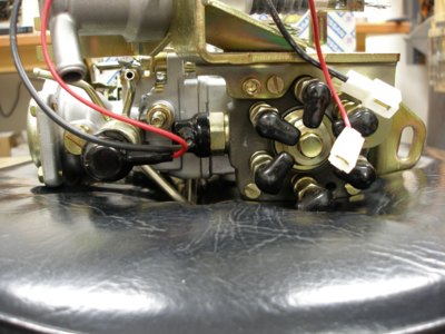
Glow plug relay
So I was preping my harness and I noticed that I have a single Glow plug relay. I have 2 large wires coming off that and a single small wire that looks to be green with a blue stripe. On the engine there is a set of 2 large white wires coming off the glow plug connectors.
I think that one of the large wires on the relay should be 12V power the small wire is the signal wire and the other large wire goes to the glow plugs. I would assume that those plugs should be on a timer circuit? Also why are there 2 wires coming off the glow plugs themselves what am I missing? is there a wire diagram for these anywhere?
Thanks
Ray
-
goglio704
- Posts: 726
- Joined: 18 years ago
- Location: East Tennessee
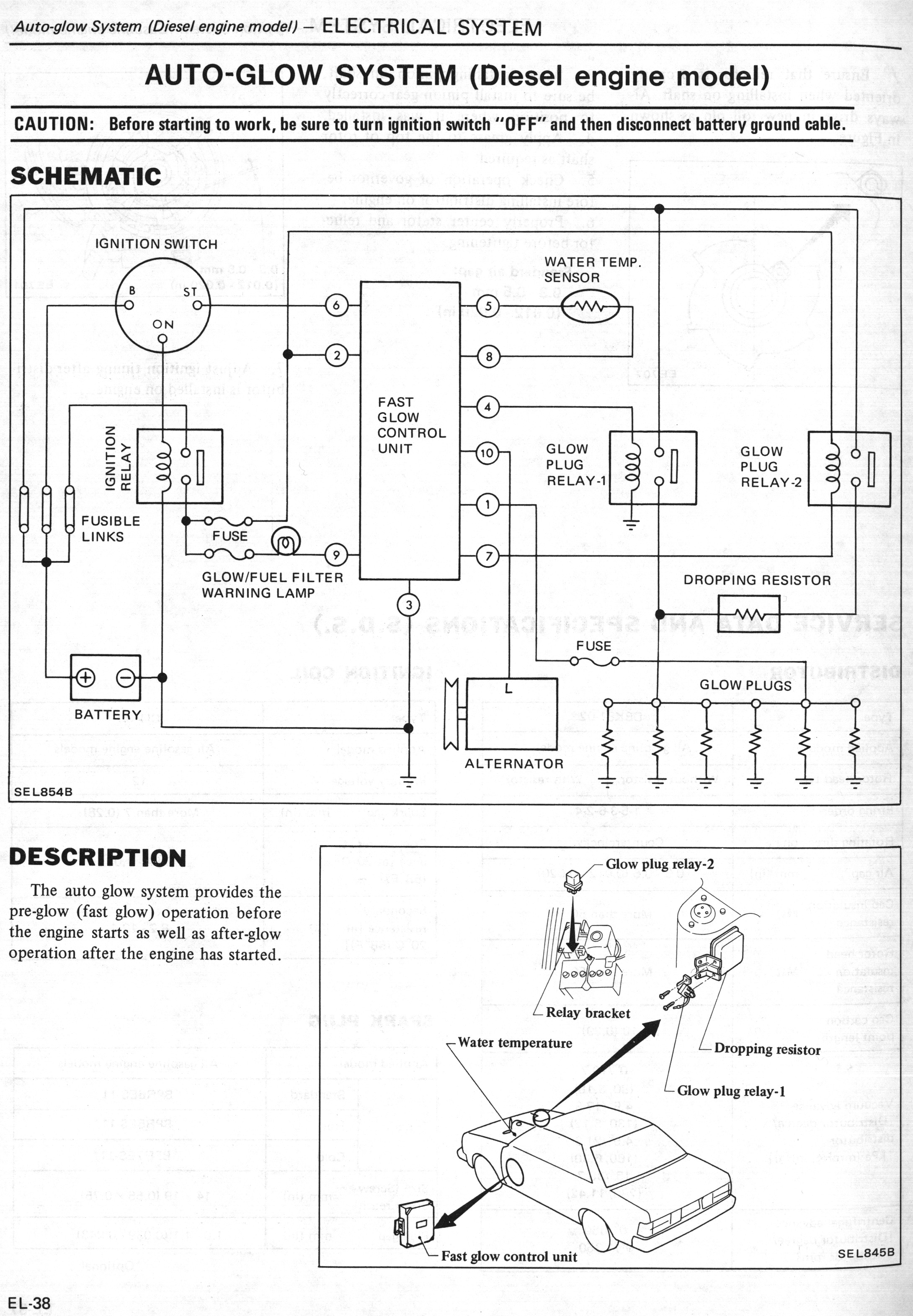
There are two heavy gauge wires going to the glowplugs because of the full voltage / reduced voltage setup. Initially, the glowplugs are energized at full voltage, but then they are energized through a dropping resistor at reduced voltage for afterglow operation. There is an electronic timer, but it resides in the passenger compartment of the Maxima. I'm assuming your engine came from a Maxima? A Maxima FSM has a good diagram of the circuit.
Matt B.
83 Maxima Sedan, LD28, 5 speed, white, 130k miles. My original Maxima.
83 Maxima Sedan converted from gasser, LD28, 5 speed, 2 tone blue, 230k miles
82 Maxima Sedan, LD28, 3 speed auto, 2 tone Gray/Silver, 140k miles
81 810 Sedan, LD28, 3 speed auto, rust, rust, and more rust!
2005 Jeep Liberty CRD
83 Maxima Sedan, LD28, 5 speed, white, 130k miles. My original Maxima.
83 Maxima Sedan converted from gasser, LD28, 5 speed, 2 tone blue, 230k miles
82 Maxima Sedan, LD28, 3 speed auto, 2 tone Gray/Silver, 140k miles
81 810 Sedan, LD28, 3 speed auto, rust, rust, and more rust!
2005 Jeep Liberty CRD
-
asavage
- Site Admin
- Posts: 5433
- Joined: 18 years ago
- Location: Oak Harbor, Wash.
- Contact:
Re: Glow plug relay
That's GP Relay 1 (Main GP Relay).DMS wrote:So I was preping my harness and I noticed that I have a single Glow plug relay. I have 2 large wires coming off that and a single small wire that looks to be green with a blue stripe. On the engine there is a set of 2 large white wires coming off the glow plug connectors.
Protected by a fusible link. At least 60A.. . . one of the large wires on the relay should be 12V power . . .
You got that all correct.. . . the small wire is the signal wire and the other large wire goes to the glow plugs. I would assume that those plugs should be on a timer circuit?
One White wire from the GP bus is to the GP Relay 1 (and also Relay 2 via the dropping resistor). The other is a voltage feedback sensing line to the GP controller.Also why are there 2 wires coming off the glow plugs themselves what am I missing?
is there a wire diagram for these anywhere?
Of course. In the Factory Service Manual. They're on eBay all the time. I also sell them, $20 including shipping USPS Media Rate. How many do you want? You have to have one.
Meanwhile, take a look at this:
1982 FSM GP Wiring Schematic
1982 FSM GP Wiring diagram
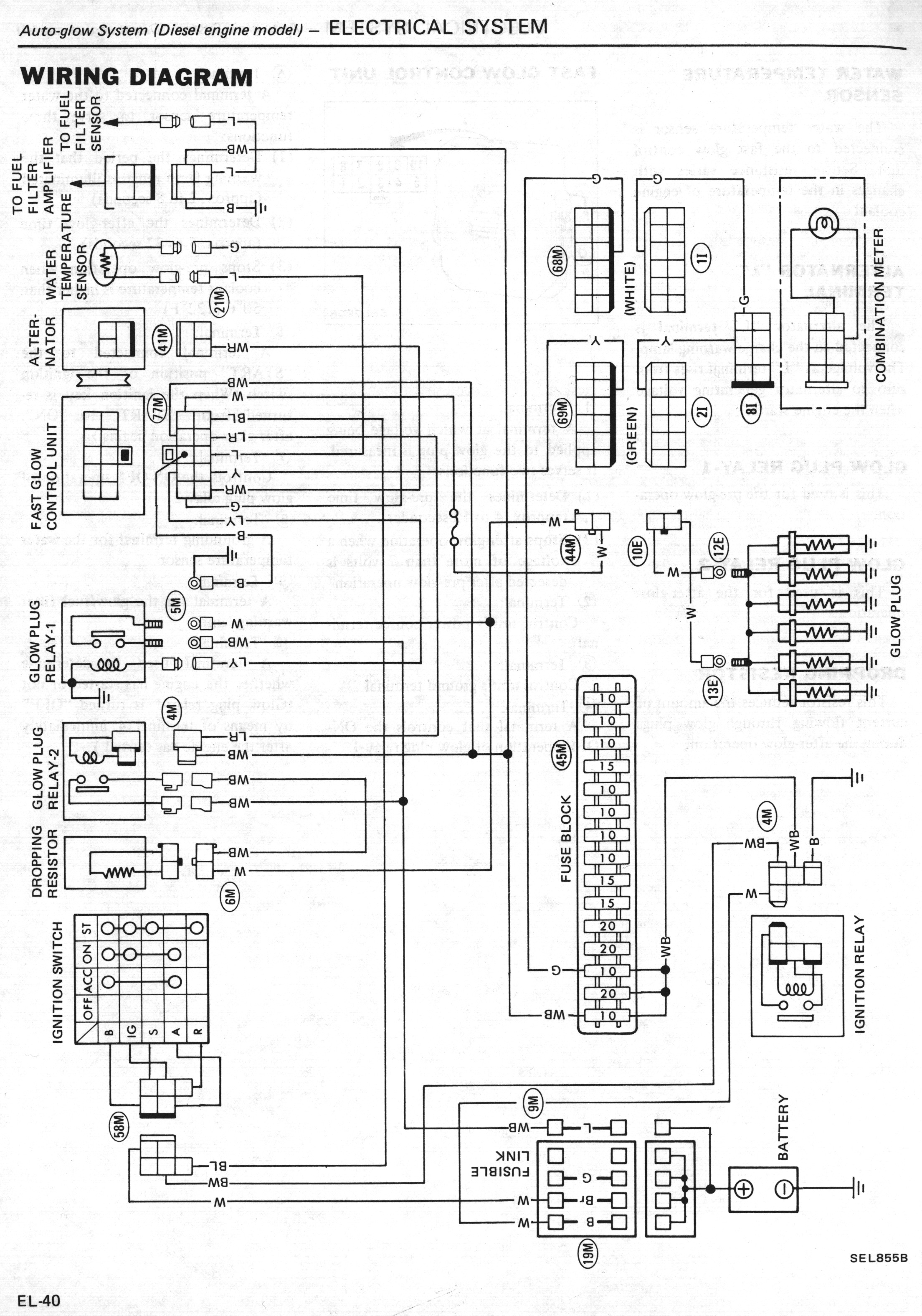
Regards,
Al S.
1982 Maxima diesel wagon, 2nd & 4th owner, 165k miles, rusty & burgundy/grey. Purchased 1996, SOLD 16Feb10
1983 Maxima diesel wagon, 199k miles, rusty, light yellow/light brown. SOLD 14Jul07
1981 720 SD22 (scrapped 04Sep07)
1983 Sentra CD17, 255k, bought 06Jul08, gave it away 22Jun10.
Al S.
1982 Maxima diesel wagon, 2nd & 4th owner, 165k miles, rusty & burgundy/grey. Purchased 1996, SOLD 16Feb10
1983 Maxima diesel wagon, 199k miles, rusty, light yellow/light brown. SOLD 14Jul07
1981 720 SD22 (scrapped 04Sep07)
1983 Sentra CD17, 255k, bought 06Jul08, gave it away 22Jun10.
-
DMS
- Posts: 117
- Joined: 17 years ago
- Location: Prunedale Ca. 93907
- Contact:
Who is online
Users browsing this forum: No registered users and 4 guests