The GPs are wired in parallel. Given a pipe (wire) of sufficient size, the pressure (voltage) at the end of the pipe should be nearly the same as at the start.
IOW, it sounds as if the wire size of the GP bus is too small. We don't expect the voltage at the starter to be three volts less than at the battery; why would we expect a three volt drop from one end of the GP system (the battery) to the other (No. 1 GP)?
When I get the SD back in the "Arlington Truck", I'm going to have to investigate this further. I have been assuming through this discussion that the drop that Lonnie had been experiencing was one or more of the poor connectors that Nissan saddled us with. From my memory, the GP wiring is all 10 gauge, which from my rule-of-thumb ought to be sufficient for a constant load of about 50a. I realize that the inrush current is better than double that, but it drops off so fast that that can be considered to be of no consequence, but if 2-3v are being lost after five seconds GP operation, it may be that the wire itself is too light to do an adequate job of getting the most out of the available voltage. Which doesn't add up, because we know the GPs settle down to a constant of, what, 15a each? Close enough to 50a total.
Perhaps the wire has aged and is no longer truly 10ga, due to environmental conditions and fatigue.
[The LD uses two 10ga wires to feed its GP bus. There's a clue: they doubled the pipe's size when the current requirement went up 50%.]
Put another way: the collective amperage draw of all the GPs should not drop the system (battery) voltage below 10.5v, and all of that 10.5+v should be available to all the GPs -- which means the total of all resistances (corrosion, connectors, terminals, contacts) between the battery and the last GP should not drop the voltage at the GPs more than (picking a number) 0.5v).
If I put 100a load on a SD's battery, it damned well better stay above 10.5v for a good long time!
Cold weather starting... Glow System checks
Moderators: plenzen, Nissan_Ranger
-
asavage

- Site Admin
- Posts: 5433
- Joined: 18 years ago
- Location: Oak Harbor, Wash.
- Contact:
Regards,
Al S.
1982 Maxima diesel wagon, 2nd & 4th owner, 165k miles, rusty & burgundy/grey. Purchased 1996, SOLD 16Feb10
1983 Maxima diesel wagon, 199k miles, rusty, light yellow/light brown. SOLD 14Jul07
1981 720 SD22 (scrapped 04Sep07)
1983 Sentra CD17, 255k, bought 06Jul08, gave it away 22Jun10.
Al S.
1982 Maxima diesel wagon, 2nd & 4th owner, 165k miles, rusty & burgundy/grey. Purchased 1996, SOLD 16Feb10
1983 Maxima diesel wagon, 199k miles, rusty, light yellow/light brown. SOLD 14Jul07
1981 720 SD22 (scrapped 04Sep07)
1983 Sentra CD17, 255k, bought 06Jul08, gave it away 22Jun10.
-
philip

- Deceased
- Posts: 1494
- Joined: 18 years ago
- Location: Southern California, USA
Recall awhile back when I did the injector job that I fabricated at new glow plug harnass ... just the one connecting the glows to each other using 12 gauge wire which is more than the OEM wire. Made no difference.asavage wrote:SNIP- From my memory, the GP wiring is all 10 gauge, which from my rule-of-thumb ought to be sufficient for a constant load of about 50a. I realize that the inrush current is better than double that, but it drops off so fast that that can be considered to be of no consequence, but if 2-3v are being lost after five seconds GP operation, it may be that the wire itself is too light to do an adequate job of getting the most out of the available voltage.
asavage wrote: Which doesn't add up, because we know the GPs settle down to a constant of, what, 15a each? Close enough to 50a total.
"Testing the glows individually, typical initial amperage draw in the first 2 seconds is 18 amps ... which falls to 5-7 amps in the span of 12-15 seconds. "
WHAT? My truck ... the one that's known only the southern California lifestyle for 25 yrs? Dudeasavage wrote: Perhaps the wire has aged and is no longer truly 10ga, due to environmental conditions and fatigue.
Here are the values I just measured during the 30 seconds the glows are ON:asavage wrote: Put another way: the collective amperage draw of all the GPs should not drop the system (battery) voltage below 10.5v, and all of that 10.5+v should be available to all the GPs -- which means the total of all resistances (corrosion, connectors, terminals, contacts) between the battery and the last GP should not drop the voltage at the GPs more than (picking a number) 0.5v).
Key OFF, volts across battery terms = 12.2v
Key ON, voltage at #1 glow starts 8.8v and stabilizes at 10v
Key ON, #1 glow voltage stabilzed, volts across battery terms = 11.8
(Next morning ... more diagnosing the missing 1.8 volts)
Key OFF, volts across battery terms = 12.2
Key ON, duty relay ON, Glow plugs connected, measurement from battery +post to duty relay power terminal = 0.6v
Key ON, duty relay ON, Glow plugs connected, measurement across heavy current terminals = 0.05v
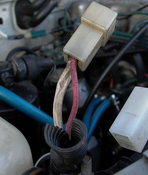
Key ON, volts across White/red wire from duty relay output terminal to glow plug bus connector = 0.6v .
Key ON, volts across glow plug wire from glow plug bus connector to #1 glow plug = 0.2v
Neither heavy current connectors showed significant voltage loss.
My battery is a group 27F (big for the tray) 725 CCA@0*.
Looks like we've found at least 1.4volts. The best bang for the buck is doing a parallel connection (as you mentioned earlier) from the glow plug bus connector to the duty relay. This IS the same wire that warms after two GP cyclings.
But do inefficiencies at this level matter THAT much? The photo I took of an installed and lighted glow plug (injector removed) reveals a bright yellow glow plug. Take a look.
Last edited by philip 17 years ago, edited 10 times in total.
-Philip
Passed 08May2008
My friend, you are missed . . .
1982 Datsun 720KC SD-22
"Im slow and I'm ahead of you"
Passed 08May2008
My friend, you are missed . . .
1982 Datsun 720KC SD-22
"Im slow and I'm ahead of you"
-
asavage
- Site Admin
- Posts: 5433
- Joined: 18 years ago
- Location: Oak Harbor, Wash.
- Contact:
I thought the OEM wire is 10ga. I'll have to look at mine today.philip wrote:Recall awhile back when I did the injector job that I fabricated at new glow plug harness ... just the one connecting the glows to each other using 12 gauge wire which is more than the OEM wire.
That's kind of low. Charged (for non-Delco wet cells) is 12.6v. At least, that's the number I've been using for years. Whatever, that isn't relevant, because . . .Here are the values I just measured:
Key OFF, volts across battery terms = 12.2v
1.8v lost between the battery terminal and the end of the GP bus. Not good: that's three times what I would consider acceptable.Key ON, voltage at #1 glow starts 8.8v and stabilizes at 10v
Key ON, #1 glow voltage stabilized, volts across battery terms = 11.8
Plenty -- on paper.My battery is a group 27F (big for the tray) 725 CCA@0*.
Thanks for taking the measurements. I was wondering.
Regards,
Al S.
1982 Maxima diesel wagon, 2nd & 4th owner, 165k miles, rusty & burgundy/grey. Purchased 1996, SOLD 16Feb10
1983 Maxima diesel wagon, 199k miles, rusty, light yellow/light brown. SOLD 14Jul07
1981 720 SD22 (scrapped 04Sep07)
1983 Sentra CD17, 255k, bought 06Jul08, gave it away 22Jun10.
Al S.
1982 Maxima diesel wagon, 2nd & 4th owner, 165k miles, rusty & burgundy/grey. Purchased 1996, SOLD 16Feb10
1983 Maxima diesel wagon, 199k miles, rusty, light yellow/light brown. SOLD 14Jul07
1981 720 SD22 (scrapped 04Sep07)
1983 Sentra CD17, 255k, bought 06Jul08, gave it away 22Jun10.
-
philip
- Deceased
- Posts: 1494
- Joined: 18 years ago
- Location: Southern California, USA
Additional voltage drop tests added to previous post. Hmmm!asavage wrote:Thanks for taking the measurements. I was wondering.
BTW, you're right about the GP bus wire gauge. It's #10 ... and I used the next thicker wire, #8 gauge. Higher # means thinner wire (
-Philip
Passed 08May2008
My friend, you are missed . . .
1982 Datsun 720KC SD-22
"Im slow and I'm ahead of you"
Passed 08May2008
My friend, you are missed . . .
1982 Datsun 720KC SD-22
"Im slow and I'm ahead of you"
-
asavage
- Site Admin
- Posts: 5433
- Joined: 18 years ago
- Location: Oak Harbor, Wash.
- Contact:
Higher number means smaller bullets!philip wrote:Higher # means thinner wire ()
Does it matter? Maybe not for your situation, but for cold climate starts with a battery that isn't the freshest, those wire losses add up.
I still don't like that 12.2v for "at rest" battery voltage. But paralleling the "bad" wires (ie from the battery terminal to the GP Relay, and from the GP Relay to the No. 4 GP) would be a Good Idea in my book.
On my '83 Wagon ("Myrna"), I inherited a lot of GP wiring junk from previous attempts to start it. I replaced the wiring from the GP Relays to the GP Bus with new, heavier wire (and replaced the GP bus bar with an Addy Rev. A copper bus) and the "Wait" light now goes off several seconds earlier than it used to. On the Maxima, it's noticeable. I took pictures of what I did, I hope to write it up someday. I'm waiting the Addy Rev. B bus to arrive first, though.
Regards,
Al S.
1982 Maxima diesel wagon, 2nd & 4th owner, 165k miles, rusty & burgundy/grey. Purchased 1996, SOLD 16Feb10
1983 Maxima diesel wagon, 199k miles, rusty, light yellow/light brown. SOLD 14Jul07
1981 720 SD22 (scrapped 04Sep07)
1983 Sentra CD17, 255k, bought 06Jul08, gave it away 22Jun10.
Al S.
1982 Maxima diesel wagon, 2nd & 4th owner, 165k miles, rusty & burgundy/grey. Purchased 1996, SOLD 16Feb10
1983 Maxima diesel wagon, 199k miles, rusty, light yellow/light brown. SOLD 14Jul07
1981 720 SD22 (scrapped 04Sep07)
1983 Sentra CD17, 255k, bought 06Jul08, gave it away 22Jun10.
-
philip
- Deceased
- Posts: 1494
- Joined: 18 years ago
- Location: Southern California, USA
Okay ... the work is done. I soldered in a parallel 10 gauge wire from the current relay to the GP bus connector. Volt loss across that segment dropped from 0.6v to 0.17v. We'll see what happens tomorrow with everything cold (... as it gets here lately, low 40's).asavage wrote:SNIP- But paralleling the "bad" wires (ie from the battery terminal to the GP Relay, and from the GP Relay to the No. 4 GP) would be a Good Idea in my book. -SNIP
Next morning ...
Truck fired right off as usual, nothing different.
Next check, the 10 gauge White wire from the battery (through the fuseable link) to duty relay. Voltage drop was still 0.6v under load.
Interesting discovery is 0.22 of that 0.6v loss was across the fuseable link.
There was no damage to the adjacent Red wire.
Last edited by philip 17 years ago, edited 2 times in total.
-Philip
Passed 08May2008
My friend, you are missed . . .
1982 Datsun 720KC SD-22
"Im slow and I'm ahead of you"
Passed 08May2008
My friend, you are missed . . .
1982 Datsun 720KC SD-22
"Im slow and I'm ahead of you"
Who is online
Users browsing this forum: Bing [Bot] and 0 guests