G'day,
Been reading what I can find on this forum about EGTs and their safe ranges etc. There appears to be a lot done on this topic in the SD section but little in the way of information on NA LD28s. A bit on turbo LDs.
I don't have nor do I intend to have, an LD28T but at the same time EGTs are of interest. The nature of some of the driving I do is off road, slow, and pulling some high revs for periods of time. Most of the time it is simply idling along climbing slow or whatever, but occasionally there are prolonged periods of high revs required to keep moving.
What are your thoughts on fitting a pyrometer on an NA LD28? I know of folk over here with Toyotas that drive off road by their pyrometer due to the possibility of head/piston issues.
Would the same hold true for LD28's? How sensitive is the LD28 to head/piston damage due to high EGTs?
Cheers,
Phil
EGTs - normally aspirated LD28
Moderators: plenzen, glenlloyd, goglio704, Nissan_Ranger
-
windsock
- Posts: 144
- Joined: 17 years ago
-
asavage

- Site Admin
- Posts: 5463
- Joined: 20 years ago
- Location: Oak Harbor, Wash.
- Has thanked: 5 times
- Been thanked: 4 times
- Contact:
Re: EGTs - normally aspirated LD28
I installed the thermocouple but never ran the wires inside. I carved the dash out to accommodate my tach and pyrometer, but it is unfinished, and I basically never drive the rig anymore. Better pictures if you click on the image below:windsock wrote:What are your thoughts on fitting a pyrometer on an NA LD28?
Regards,
Al S.
1982 Maxima diesel wagon, 2nd & 4th owner, 165k miles, rusty & burgundy/grey. Purchased 1996, SOLD 16Feb10
1983 Maxima diesel wagon, 199k miles, rusty, light yellow/light brown. SOLD 14Jul07
1981 720 SD22 (scrapped 04Sep07)
1983 Sentra CD17, 255k, bought 06Jul08, gave it away 22Jun10.
Al S.
1982 Maxima diesel wagon, 2nd & 4th owner, 165k miles, rusty & burgundy/grey. Purchased 1996, SOLD 16Feb10
1983 Maxima diesel wagon, 199k miles, rusty, light yellow/light brown. SOLD 14Jul07
1981 720 SD22 (scrapped 04Sep07)
1983 Sentra CD17, 255k, bought 06Jul08, gave it away 22Jun10.
-
windsock
- Posts: 144
- Joined: 17 years ago
Hi Al,
Is that a stock LD28 zorst manifold for you guys over there?
I have one slightly different. The appears to be a fitting on your one to the left of where you've mounted your thermocouple. What is that? It is not present on my manifold (nor on my spares).
Also, about where you've drilled on your one (perhaps just a bit above it), on the inside is there like a small raised bit of steel about 18mm dia and 12mm high? Almost looks like it is intended to create turbulence in the flow as the two portions 'merge' into the two-into-one exhaust tube. If you have this raised bit on your manifold, where exactly did the thermocouple get drilled relative to this? Would it matter?
Cheers,
Phil
Good roads lead to bad fishing.
-
asavage
- Site Admin
- Posts: 5463
- Joined: 20 years ago
- Location: Oak Harbor, Wash.
- Has thanked: 5 times
- Been thanked: 4 times
- Contact:
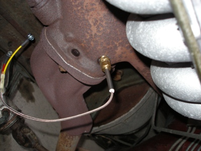
EGR feed tube. It's SS and runs up to an EGR flow control valve on the intake manifold near the inlet.windsock wrote:Is that a stock LD28 zorst manifold for you guys over there?
I have one slightly different. The appears to be a fitting on your one to the left of where you've mounted your thermocouple. What is that? It is not present on my manifold (nor on my spares).
I can't answer your other Q.
-
windsock
- Posts: 144
- Joined: 17 years ago
G'day Al,asavage wrote:EGR feed tube. It's SS and runs up to an EGR flow control valve on the intake manifold near the inlet.windsock wrote:Is that a stock LD28 zorst manifold for you guys over there?
I have one slightly different. The appears to be a fitting on your one to the left of where you've mounted your thermocouple. What is that? It is not present on my manifold (nor on my spares).
I can't answer your other Q.
OK, I figure the both sides of my exhaust manifold have the "bump" in the same position so I figure it is to break up any laminar flow in the gases to allow for proper merging, or to increase turbulence to the point where the flows are equally turbulent - something like that...
Anyways, I took a photo this morning of these appendages and estimated where your thermocouple would be. I am unsure of where to drill one relative to these bumps.

Any thoughts? I would say if in any immediate proximty then directly downstream and tucked up as close as can be done. If nothing else, it provides a bit of extra steel to tap into.
If not immediately downstream then quite possibly as far as is possible to get from it.
While we're looking at this end of the engine, what is the general consensus out there about exhaust tube sizing? I have tapped into the Land Rover 2 inch system but the main muffler needs replacing and was wondering whether I should consider a slightly larger size diameter pipe also. I realise back pressure is vital etc. I would estimate the overall length of exhaust system I have would be about 700mm longer than that which was in the car. I also run a spark arrestor type smaller muffler on the last metre of my system.
Cheers,
Phil
Good roads lead to bad fishing.
-
windsock
- Posts: 144
- Joined: 17 years ago
Hi Rufus,rlaggren wrote:Why hide the probe behind the bump? Just curious.
Rufus
Probe wouldn't be hidden as such behind the bump but the probe mounting piece would be. The probe would be full into the flow of gas so wouldn't matter. I figure the bumps are there for a reason and I figure the reason is flow related. Cannot figure out any other reason for putting a bump there in both outlets.
Good roads lead to bad fishing.
-
davehoos
- Posts: 525
- Joined: 20 years ago
- Location: Karuah Valley,NSW Australia
- Contact:
-
windsock
- Posts: 144
- Joined: 17 years ago
G'day Davehoos,
Cheers,
Phil
You know, you could be right there. They could be intended for drilled/tapped holes that don't go right into the exhaust flow. Makes sense as another option for their being there.davehoos wrote:i think the bump is part of a heat sheild option.or the molding process.
Likewise I have a 3 into 1 for each of the cylinders 1, 2, & 3 and then 4, 5, & 6. These then go into one within the first 10 inches of exhaust tubing. I figured an EGT probe would be best as close to the hotter gases as I could get so I figure cylinders 4, 5, & 6 would be the hottest being further away from the cooling airflow all things being equal.would the egt be better after the joning point in the engine pipe???
australian models have twin engine pipes-not much good for you.
about meter long before they join to assist with hyway running.
Cheers,
Phil
Good roads lead to bad fishing.
-
windsock
- Posts: 144
- Joined: 17 years ago
OK, drilled the hole today... after picking up a VDO pyrometer yesterday.
Figured if I could get the probe to go from roughly centre of this bump...

...to be over the centre of this hollow I'd have all three cylinders 4, 5, and 6 covered for EGT

Got it just off centre but the probe hovers just above the hollow now

Unfortunately I forgot to take a shot of the probe inside the manifold in place but its there alright.


While I had the manifold off I tightened the leaky oil pipe and was going to clean the air intake gunge if needed. Was surprisingly clean in there though so just put it all back on.

Took it all for a test run and it runs sweet. I had a leaky manifold so when I put it all back I was sure to use a good gasket and tightened all the bolts and nuts up. A few were loose so thats why it leaked.
EGT (in Deg C) on normal running varied between 250 (flat road cruise - 50kph in town) to 400 open road cruise 95kph, to 550 for up hill in fourth, 450 up hill in third.
All in all a pleasing and relatively quick addition to the information. it'll come in handy for the hard work this truck and engine does when 4X4.
I'll fill in some details later on when not busy with work.
Figured if I could get the probe to go from roughly centre of this bump...
...to be over the centre of this hollow I'd have all three cylinders 4, 5, and 6 covered for EGT
Got it just off centre but the probe hovers just above the hollow now
Unfortunately I forgot to take a shot of the probe inside the manifold in place but its there alright.
While I had the manifold off I tightened the leaky oil pipe and was going to clean the air intake gunge if needed. Was surprisingly clean in there though so just put it all back on.
Took it all for a test run and it runs sweet. I had a leaky manifold so when I put it all back I was sure to use a good gasket and tightened all the bolts and nuts up. A few were loose so thats why it leaked.
EGT (in Deg C) on normal running varied between 250 (flat road cruise - 50kph in town) to 400 open road cruise 95kph, to 550 for up hill in fourth, 450 up hill in third.
All in all a pleasing and relatively quick addition to the information. it'll come in handy for the hard work this truck and engine does when 4X4.
I'll fill in some details later on when not busy with work.
Good roads lead to bad fishing.
-
rlaggren
- Posts: 541
- Joined: 19 years ago
- Location: San Francisco
250 C. = 450 F.
400 C. = 720 F.
450 C. = 800 F.
550 C. = 990 F.
Congrats. Thanks for the great pics.
How'd you locate the spot to drill (from the outside). Any particular tricks? If you used measures, maybe you could post a list or pic of your working sketch - give the next guy a reality check.
Cheers, Rufus
400 C. = 720 F.
450 C. = 800 F.
550 C. = 990 F.
Congrats. Thanks for the great pics.
How'd you locate the spot to drill (from the outside). Any particular tricks? If you used measures, maybe you could post a list or pic of your working sketch - give the next guy a reality check.
Cheers, Rufus
82 Maxima wagon
-
windsock
- Posts: 144
- Joined: 17 years ago
G'day Rufus,
Yeah OK, measurements.
First point to note caveat emptor, measurements are approx only and this advice is worth what was paid etc etc all the usual caveats
From the outside of the flange to the centre of the bump is approx 53mm.
The next dimension is easier to showw with a photo so...

50mm in from the line of the outer back edge of the manifold. Sorry guys best I can do now that it is installed again. I missed where I was aiming due to not allowing for a slight angle downwards towards the small hollow. I got the end of the probe in approx the right place but I was aiming to drill my hole into the more steel available from the bump. As it was, I got approx six threads into the thinnest peice of wall. I used a tapered tap to do the thread for the tapered probe fitting. I was especially careful how far I tapped into it to make sure I didn't tap too far and end up running out of thread on the adpater before it was tight if you know what I mean.
Hope this helps somewhat.
Cheers,
Phil
Yeah OK, measurements.
First point to note caveat emptor, measurements are approx only and this advice is worth what was paid etc etc all the usual caveats
From the outside of the flange to the centre of the bump is approx 53mm.
The next dimension is easier to showw with a photo so...
50mm in from the line of the outer back edge of the manifold. Sorry guys best I can do now that it is installed again. I missed where I was aiming due to not allowing for a slight angle downwards towards the small hollow. I got the end of the probe in approx the right place but I was aiming to drill my hole into the more steel available from the bump. As it was, I got approx six threads into the thinnest peice of wall. I used a tapered tap to do the thread for the tapered probe fitting. I was especially careful how far I tapped into it to make sure I didn't tap too far and end up running out of thread on the adpater before it was tight if you know what I mean.
Hope this helps somewhat.
Cheers,
Phil
Good roads lead to bad fishing.
Who is online
Users browsing this forum: No registered users and 1 guest