I got my truck in March of 2004 (120k odometer). At 125k miles, I replaced all 8 oil seals, using the K-D tool. Since I was getting familiarized with this truck, I did not take a few photos.
Today I removed my valve cover to look at the valve train (179k miles). Sorry but I could not get close enough with a camera without removing the rocker assemble. So I used a small bright flash and mirror.
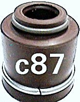
My oil seals are black color with a circlip at the bottom of the cup. Mine do not have the little lip spring shown here.
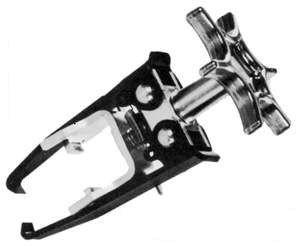
Here is the nifty K-D valve spring compressor so that you don't have to pull off the cylinder head.
(Valve Spring Compressor K-D Tools 2078 - Universal Overhead)
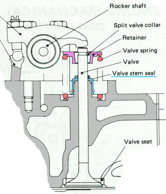
This is the way Nissan designed it. Notice the oil seal cup fits around the valve guide and extends almost to the bottom (valve spring retainer - cylinder head).
-Philip Passed 08May2008
My friend, you are missed . . .
1982 Datsun 720KC SD-22
Don’t mean to butt in here, but, here is how I/we did it “back in the day”. There may be another way but,,,,,,,,,,,, Remove the rocker shaft and push rods. Use two push rods to measure cam travel for any cylinder. I mean to re-insert them back onto the lifters for that cylinder. You can start on any cyl you like. Rotate the engine slowly in the correct rotation until the two rods are just changing over. (Exh closed or at the bottom of it's travel, and intake just starting to move upwards). That piston, for that cyl, will be at the top, and, the cyl opposite to it will also be at the top. EG: If #1 exh is closed or at the bottom of its travel and the intake is just starting to move then #4 will be at TDC, and #1 will be just starting on the “intake stroke”, and, the piston will still be at the top of the bore, or very near to it (depending on cam overlap). You can then change both sets of valve seals for cyls #1 and #4. Then do the same with #2 and #3.
The one thing that you have to watch carefully is that you in fact have the push rods in the right holes for the cylinder that you are watching. Easy to miss a hole and have them on two intakes for adjoining cylinders or two exhausts. Then, when you remove the keepers and you hear this horrible sickening metalic "clink" and the valve stem is no longer visible you are now buying a head gasket. BTDT!!!
That is how I/we used to do it anyway.
There may be a more scientific approach though.
Paul.
Retired Pauly
Problem with being retired is that you never get a day off.
1987 D21-J SD25 KC
KJLGD21FN
cseger1 wrote:Thanks for the link. How do you tell when the cylinder you're working on is at TDC?
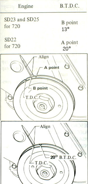
Another reason you might ask for finding TDC is for setting your injection pump.
You are at the level now where OWNING a Datsun / Nissan Service Manual of you very own! Not one of those cheap Chiltons or Hayes, but a real FMS (Factory Manual Service) which Al finds them on ebay quite often.
-Philip Passed 08May2008
My friend, you are missed . . .
1982 Datsun 720KC SD-22
I guess an easier way for the 4cyl engine would be to simply line up the timing mark at 0 and then piston #'s 1 and 4 will be at the top and then rotate the engine 180 degrees (will have to go and research how to make that little symbol again) and #'s 2 and 3 will be at the top. The previous method of watching the rockers change will work well for setting valves too. Rock 1 set 4, rock 2 set 3, rock 3 set 2, rock 4 set 1. I was thinking of 6's and V8's previously. Sorry, brain is not what it used to be.
Found it! alt down +248 = ° !!!
Thanks again Al
Paul
Retired Pauly
Problem with being retired is that you never get a day off.
1987 D21-J SD25 KC
KJLGD21FN
Knowing where TDC is is completely unnecessary to adjust the valve lash, if you use an alternate procedure, which, while requiring you to move the crankshaft a lot more times, works on any engine with valves.
Pick a valve to adjust;
Rotate crank until that valve is fully open (pushed down). Not necessary to be exact. Good shop practice is to rotate it in the normal running direction;
Note approximate situation of crank sheave;
Rotate crank exactly one turn;
Adjust valve lash;
Repeat for other valves.
The reason this works is that you are placing each valve on the base circle of the cam's lobe, for every valve in turn. Since the base circle encompasses at least 180° of the cam's rotation, you don't have to be exactly on the spot, but do try anyway.
Doesn't require precise placement of the crankshaft (as does the FSM method) or finding the timing marks on the sheave or flywheel, and works with every four-cycle engine that uses valves. Might not work with 2-cycle diesels, I just haven't looked into it. The primary disadvantage of this method is having to rotate the crank so many times.
Your right Al. Your way you can do all 8 valves with one crankshaft rotation, and my way will require two complete turns. I was originally just trying to help with piston placement in the cylinders for when the valve seals were being replaced. IE: at the top so valve does not fall inside. That valve adjustment procedure was a way that was taught to me when I was just begining, and, an easy way to remember, for me at least. Take any firing order be it for a 4, 6, 8, or 12 cyl. Split the order in half. Take the first half of the firing order and write it down on a piece of paper, and write the second half of the firing order under the first numbers. Those two numbers (above and below) are the "opposite" of each other and "rocking" the valves on one of those cylinders will mean that the lobes of the camshaft of the "opposite" cylinder will be at the bottom. EG: Chev SB V8 Firing order is - 1 8 4 3 / 6 5 7 2. Rock 1 set 6 rock 8 set 5 rock 4 set 7 and so on. Then comming back the other way rock 6 set 1 rock 5 set 8,,,,, you get the idea.
Paul
Retired Pauly
Problem with being retired is that you never get a day off.
1987 D21-J SD25 KC
KJLGD21FN