Al, thank you for your recognition.
I will donate any kickbacks, should they materialize, back to this forum.
Cruise Control RPM pickup on LD28 maxi's for tach?
Moderators: plenzen, glenlloyd, goglio704, Nissan_Ranger
-
dieseldorf

- Posts: 192
- Joined: 18 years ago
- Location: Oracle, AZ
Astro Van with LD28 propulsion
'84 Mercedes 190D 2.2L 5-Speed Manual purchased 06/12 SOLD 06/13
'86 Ford Escort Wagon Diesel MT Sold 07-17-08
'84 Mercedes 190D 2.2L 5-Speed Manual purchased 06/12 SOLD 06/13
'86 Ford Escort Wagon Diesel MT Sold 07-17-08
-
RacnJsn95
- Posts: 37
- Joined: 17 years ago
- Location: Central Point, OR
- Contact:
How much do you plan on selling these for? If I can find a gas Maxima cluster in a junkyard or perhaps ebay, and this might work, I'd buy one.asavage wrote:Others: I bought enough raw parts to build ten of these. For '81-82 Maximas, I can offer pre-modded controllers on an exchange basis. The parts cost is nil: even brand-new parts, with shipping, the per-unit cost is only about four dollars. It's all labor. Chris will receive a kicback for every unit I mod: it would not have been possible without his input, he did all the heavy lifting.
82 Maxima Diesel, Auto 164k
77 620 k/c 4x4, 4spd, L20b (wishes it was an LD20)
77 620 k/c 4x4, 4spd, L20b (wishes it was an LD20)
-
asavage

- Site Admin
- Posts: 5452
- Joined: 19 years ago
- Location: Oak Harbor, Wash.
- Has thanked: 2 times
- Been thanked: 3 times
- Contact:
The parts are cheap, it's only my time to assemble and test.
I'm thinking I can assemble, test, and ship these for about $30 out the door (includes shipping in the lower 48 ), exchange of course (I need to get units back for the next guy). If I start doing this, I guess I'll have to fix my EGR Rev Sensor on my '82 so I can test easily. Or buy another Maxima
The gasser clusters are relatively easy to buy at JYs. They will bolt in physically to the diesels, but I haven't looked into the cluster plugs to see what has to be cut to get the "Wait" light to be mapped to some other light.
Or, I can send a baggie of all the parts including the bare board for $6 + postage, and one can assemble it yourself.
Regards,
Al S.
1982 Maxima diesel wagon, 2nd & 4th owner, 165k miles, rusty & burgundy/grey. Purchased 1996, SOLD 16Feb10
1983 Maxima diesel wagon, 199k miles, rusty, light yellow/light brown. SOLD 14Jul07
1981 720 SD22 (scrapped 04Sep07)
1983 Sentra CD17, 255k, bought 06Jul08, gave it away 22Jun10.
Al S.
1982 Maxima diesel wagon, 2nd & 4th owner, 165k miles, rusty & burgundy/grey. Purchased 1996, SOLD 16Feb10
1983 Maxima diesel wagon, 199k miles, rusty, light yellow/light brown. SOLD 14Jul07
1981 720 SD22 (scrapped 04Sep07)
1983 Sentra CD17, 255k, bought 06Jul08, gave it away 22Jun10.
-
asavage
- Site Admin
- Posts: 5452
- Joined: 19 years ago
- Location: Oak Harbor, Wash.
- Has thanked: 2 times
- Been thanked: 3 times
- Contact:
I just assembled a second board, the RTV is curing, and I'd say it takes me about 70 minutes from start to finish, including gathering and putting away tools, and cleanup.


Last edited by asavage 17 years ago, edited 2 times in total.
-
RacnJsn95
- Posts: 37
- Joined: 17 years ago
- Location: Central Point, OR
- Contact:
I figure this would be a good "starter" project for me to learn to solder stuff like this. Eventually I want to be able to build a megasquirt, and stuff like that for a couple of my projects in the near future.
I wish I would have seen the $6 bag of parts sooner. I just ordered the stuff from digikey, but since the minimum quantity was 5 on most of the items, I ordered enough parts to make 5... Guess I'll get lots of practice.
I wish I would have seen the $6 bag of parts sooner. I just ordered the stuff from digikey, but since the minimum quantity was 5 on most of the items, I ordered enough parts to make 5... Guess I'll get lots of practice.
82 Maxima Diesel, Auto 164k
77 620 k/c 4x4, 4spd, L20b (wishes it was an LD20)
77 620 k/c 4x4, 4spd, L20b (wishes it was an LD20)
-
asavage
- Site Admin
- Posts: 5452
- Joined: 19 years ago
- Location: Oak Harbor, Wash.
- Has thanked: 2 times
- Been thanked: 3 times
- Contact:
With Chris' recipe, some basic electronics tools, and patience, it cooks itself  My challenge has always been the mirror-image problem when working on the backside of the circuit board.
Tip: try mouser.com, they have much better small-order processing than Digi-Key. No minimum order, no small-order surcharge. Std. shipping takes a full week to get to us though, and Mouser won't tell you how much the shipping is until well after the order is placed . . . but the shipping is quite reasonable for all that.
For larger orders, I use Newark, but since I don't work in that field anymore, I don't have "large" orders these days.
-
Carimbo
- Posts: 467
- Joined: 19 years ago
Sure, why not? Well, of course not while it's waiting for the rebuilt crankshaft damper. Give it a week or two.asavage wrote:Maybe I can get Carimbo to come over with his '82 Sedan.
Yours doesn't but mine does need repl. IP belt/tensioner.asavage wrote:And I am not up for pulling my IP belt sprocket only to change the rev sensor (recall that I have a tach pickup on my alternator on this car anyway, and I changed the IP belt only 15k ago).
Can do, as soon as I get it running again.asavage wrote:Carimbo: this EGR Controller mod might enable your fantasy of installing that '83 gasser cluster with factory gasser tach, and making it work. And you might throw an ohmmeter on the connections I show above, the EGR Rev Sensor leads, and make sure yours is not open as mine is.
-
asavage
- Site Admin
- Posts: 5452
- Joined: 19 years ago
- Location: Oak Harbor, Wash.
- Has thanked: 2 times
- Been thanked: 3 times
- Contact:
No need to wait: disconnect the two bullet connectors for the EGR Rev Sensor near the battery (so the sensor is no longer in circuit), set your DVOM to ohms, connect probes to the blue and green wires.Carimbo wrote:Can do, as soon as I get it running again.asavage wrote:you might throw an ohmmeter on the connections I show above, the EGR Rev Sensor leads, and make sure yours is not open as mine is.
I will get a reading on my new one tomorrow, for comparison.

-
dieseldorf
- Posts: 192
- Joined: 18 years ago
- Location: Oracle, AZ
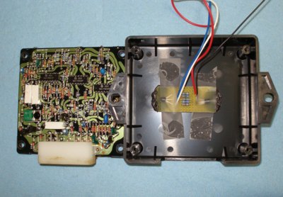
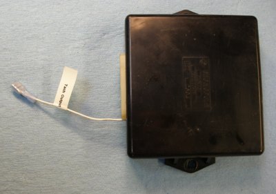
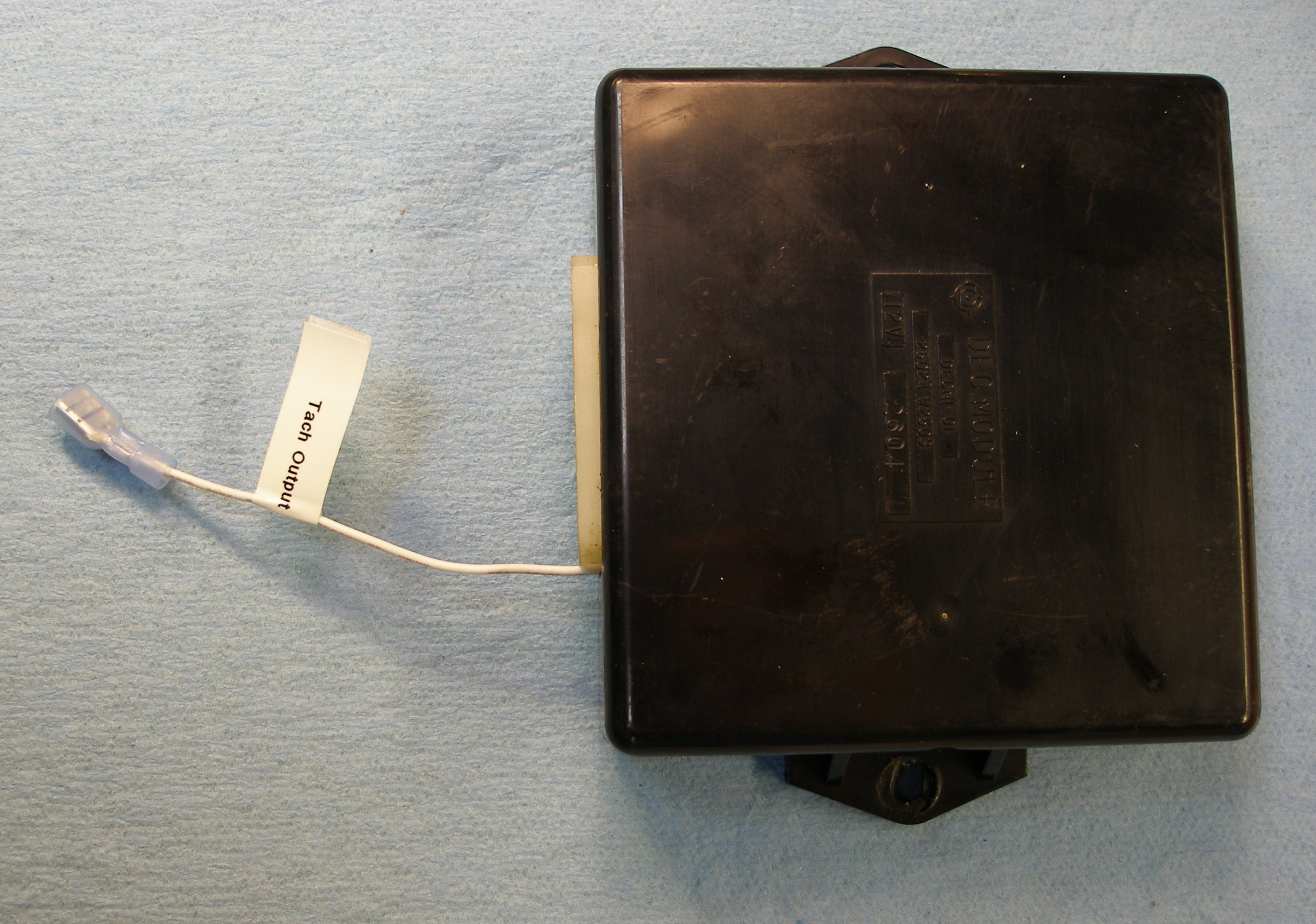
'83 EGR control module
Al,
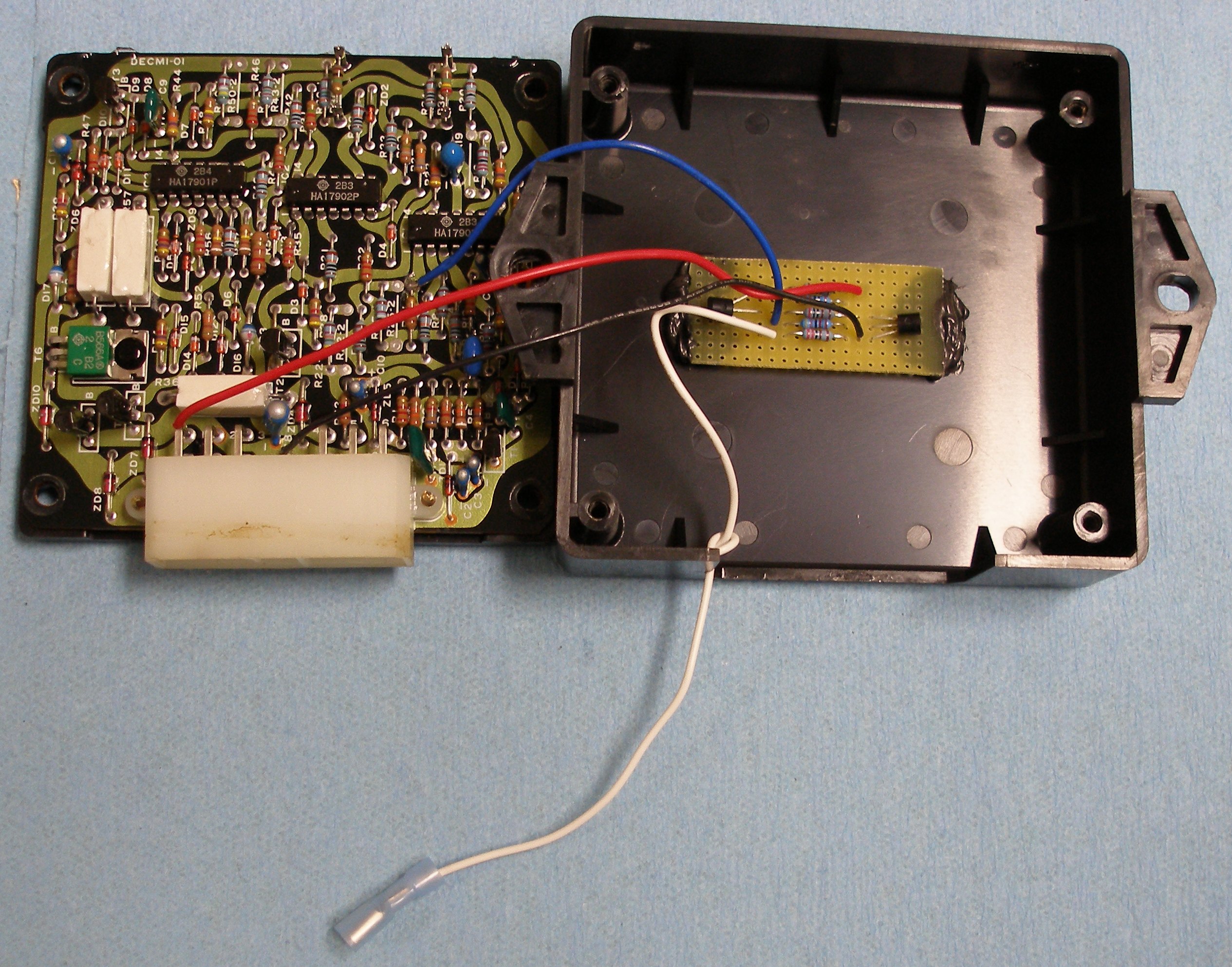
I received the '83 EGR control unit today and went ahead to test it. The PCB layout is slightly different but the sensor input circuit is the same. However, a few component values have changed making the sensor amplifier less sensitive. Whereas the '81-'82 control unit needs as little as 200mV input pulse, the '83 needs no less than 500mV input voltage. I am wondering if the '83 Maxima uses a different speed sensor with more output voltage (higher inductance). My sensor ('82) measures 1340 Ohms (1.34k) and 550mH inductance.
Conclusion: The '83 EGR control unit can be used for engine-tach modification. The buffer circuit PCB connects to the '83 controller in the same manner, same connector pins and component numbers.
Astro Van with LD28 propulsion
'84 Mercedes 190D 2.2L 5-Speed Manual purchased 06/12 SOLD 06/13
'86 Ford Escort Wagon Diesel MT Sold 07-17-08
'84 Mercedes 190D 2.2L 5-Speed Manual purchased 06/12 SOLD 06/13
'86 Ford Escort Wagon Diesel MT Sold 07-17-08
-
asavage
- Site Admin
- Posts: 5452
- Joined: 19 years ago
- Location: Oak Harbor, Wash.
- Has thanked: 2 times
- Been thanked: 3 times
- Contact:
Re: '83 EGR control module
Nissan FAST lists only the one part No. for the Rev Sensor, all years. [shrug]dieseldorf wrote:I am wondering if the '83 Maxima uses a different speed sensor with more output voltage (higher inductance).
-
RacnJsn95
- Posts: 37
- Joined: 17 years ago
- Location: Central Point, OR
- Contact:
Well I started on one for myself today... Definitely need a better soldering iron if I ever want to think about attempting to make a megasquirt! I just put in the resistors... Do they have to be in a certain way? I was trying to match up my gold stripes the same direction as the one Dieseldorf made from the pics on the first page, but I got the first and last ones backwards from the pic  I know some stuff goes one way only, but couldn't remember about resistors.

This is definitely the hardest thing I've ever done... Too bad it's not more like TIG welding
This is definitely the hardest thing I've ever done... Too bad it's not more like TIG welding
82 Maxima Diesel, Auto 164k
77 620 k/c 4x4, 4spd, L20b (wishes it was an LD20)
77 620 k/c 4x4, 4spd, L20b (wishes it was an LD20)
-
asavage
- Site Admin
- Posts: 5452
- Joined: 19 years ago
- Location: Oak Harbor, Wash.
- Has thanked: 2 times
- Been thanked: 3 times
- Contact:
Resistors are not polar: you can put them in circuit either direction. You have inserted them correctly (I checked your color codes).
The transistors, however, must be installed as shown in Chris' diagram, or they will become wires (short out) the first time power is applied! And they are different from each other (Q1 & Q2), of course, and cannot be interchanged.
You soldered to the pads, which isn't necessary. But it does hold the resistors in place (ie it doesn't hurt anything to solder them) while you work on the four wires and two transistors. Depending upon the wire gauge you use for the four wires, you may need to drill the holes for the wires to go through (which is easy if you have a pin vise and very small bits; not so easy if you don't). If you use small enough wires, this won't be necessary.
I bought a prototyping board without solder pads. The component lead lengths are such, and the circuit is laid out so well (Thanks, Chris!) that nothing serpentine is involved: the leads can be directly soldered to each other.
Tip: resistors can take a lot of heat, so you can take your time soldering them. However, semiconductors generally can't. Practice soldering small wires until you are comfortable doing a good job quickly. Alternatively, you can buy a small clip-on doo-dad that is basically a very very small pair of Vice-Grips without serrations, which you clip on on transistor's wire while soldering it, and it acts as a heat sink and prevents the heat from the soldering process to make it up to the transistor. It used to be a common soldering tool back in the days of discrete electronics, but is largely not seen anymore due to the proliferation integrated circuits. IOW, you pretty much get to be very good at soldering quickly or you find another career these days.
Anyway . . . solder the transistor legs fast, do not dally. Or have someone heat-sink each leg as you solder it, have them use needle-nose pliers on the leg on one side of the board whilst you solder on the other. Using needle-nose, you need two people, because you can't hold the pliers and solder and solder pen unless you have prehensile parts other than hands
You should not be using a $10 iron for this kind of work. The low end of an acceptable iron runs about $50, and there are a lot of decent irons in the $50 to $100 range. I like the Wellers, but my old iron is kind of antiquated by today's stds (it has "adjustable" temp, adjustable by changing tips! That's the way it was done 20 yrs ago); new rigs all have a pot to change temp, and the fancier ones have digital readout of the tip temp. You don't really need adjustable temp nor readout to do a good job though, but an iron that has replaceable tips and regulated temperature (whatever method the iron does it) is mandatory.
(I own an expensive de-soldering set, that I bought brand-new for about a thousand bux, and it has sat in storage for nine years I just don't do enough de-soldering to justify setting it up again. Runs on compressed air to generate vacuum. When I was doing bench repair for a living, it paid for itself fast. Now I use a cheap $25 solder-sucker which works quite well too, for light-duty work. I hardly touch boards anymore.)
I used a PanaVise to hold the board while soldering, just because I have one in the shop. Makes this kind of work much easier.
Keep us apprised of your progress. I still haven't tested either of mine.
The transistors, however, must be installed as shown in Chris' diagram, or they will become wires (short out) the first time power is applied! And they are different from each other (Q1 & Q2), of course, and cannot be interchanged.
You soldered to the pads, which isn't necessary. But it does hold the resistors in place (ie it doesn't hurt anything to solder them) while you work on the four wires and two transistors. Depending upon the wire gauge you use for the four wires, you may need to drill the holes for the wires to go through (which is easy if you have a pin vise and very small bits; not so easy if you don't). If you use small enough wires, this won't be necessary.
I bought a prototyping board without solder pads. The component lead lengths are such, and the circuit is laid out so well (Thanks, Chris!) that nothing serpentine is involved: the leads can be directly soldered to each other.
Tip: resistors can take a lot of heat, so you can take your time soldering them. However, semiconductors generally can't. Practice soldering small wires until you are comfortable doing a good job quickly. Alternatively, you can buy a small clip-on doo-dad that is basically a very very small pair of Vice-Grips without serrations, which you clip on on transistor's wire while soldering it, and it acts as a heat sink and prevents the heat from the soldering process to make it up to the transistor. It used to be a common soldering tool back in the days of discrete electronics, but is largely not seen anymore due to the proliferation integrated circuits. IOW, you pretty much get to be very good at soldering quickly or you find another career these days.
Anyway . . . solder the transistor legs fast, do not dally. Or have someone heat-sink each leg as you solder it, have them use needle-nose pliers on the leg on one side of the board whilst you solder on the other. Using needle-nose, you need two people, because you can't hold the pliers and solder and solder pen unless you have prehensile parts other than hands
You should not be using a $10 iron for this kind of work. The low end of an acceptable iron runs about $50, and there are a lot of decent irons in the $50 to $100 range. I like the Wellers, but my old iron is kind of antiquated by today's stds (it has "adjustable" temp, adjustable by changing tips! That's the way it was done 20 yrs ago); new rigs all have a pot to change temp, and the fancier ones have digital readout of the tip temp. You don't really need adjustable temp nor readout to do a good job though, but an iron that has replaceable tips and regulated temperature (whatever method the iron does it) is mandatory.
(I own an expensive de-soldering set, that I bought brand-new for about a thousand bux, and it has sat in storage for nine years
I used a PanaVise to hold the board while soldering, just because I have one in the shop. Makes this kind of work much easier.
Keep us apprised of your progress. I still haven't tested either of mine.
-
asavage
- Site Admin
- Posts: 5452
- Joined: 19 years ago
- Location: Oak Harbor, Wash.
- Has thanked: 2 times
- Been thanked: 3 times
- Contact:
Mark Hartz brought over his '83 today, and we plugged in the two modded EGR controllers and connected a tach to them, they work great! I had the Tach-N-Time hooked up as a cross-check, and 2k = 2k on both.
So, for fun, Mark & I built a third DieselDorf board for his '83 EGR Controller -- RTV is drying, but I'll put it together for him in the AM. Someday, he will want a tach in his Sedan.
Still takes me about an hour, all told.
So, for fun, Mark & I built a third DieselDorf board for his '83 EGR Controller -- RTV is drying, but I'll put it together for him in the AM. Someday, he will want a tach in his Sedan.
Still takes me about an hour, all told.
Regards,
Al S.
1982 Maxima diesel wagon, 2nd & 4th owner, 165k miles, rusty & burgundy/grey. Purchased 1996, SOLD 16Feb10
1983 Maxima diesel wagon, 199k miles, rusty, light yellow/light brown. SOLD 14Jul07
1981 720 SD22 (scrapped 04Sep07)
1983 Sentra CD17, 255k, bought 06Jul08, gave it away 22Jun10.
Al S.
1982 Maxima diesel wagon, 2nd & 4th owner, 165k miles, rusty & burgundy/grey. Purchased 1996, SOLD 16Feb10
1983 Maxima diesel wagon, 199k miles, rusty, light yellow/light brown. SOLD 14Jul07
1981 720 SD22 (scrapped 04Sep07)
1983 Sentra CD17, 255k, bought 06Jul08, gave it away 22Jun10.
Who is online
Users browsing this forum: Google [Bot] and 1 guest