Between three households we run three of the EU6500is and one EU7000. I recently bought and installed a four-function aftermarket wireless remote kit from Pinellas Power Products on the EU6500is at my mother's place.
The EU6500is Owner's Manual (pg. 29) states:
The Pinellas Power Products' ("PPP") 4-function wireless remote kit can control EcoThrottle mode, and at startup it defaults to Standard Run mode. The idea, I guess, is that you start the gen via the wireles remote, then wait a couple of minutes, then press the remote's EcoThrottle button to toggle the gen to EcoThrottle mode.EU6500is Owner's Manual, page No. 29 wrote:"If you wish to use the EcoThrottle system, turn the EcoThrottle switch to the ON position after the engine has warmed up for 2 or 3 minutes.
My mother knows how to start and stop and refuel her gen, but at 79 I try to automate what can be automated for her. So, I installed a time delay relay (TDR) module that runs the gen in Standard Run mode for 2.5 minutes, then switches to EcoThrottle mode automatically.
This gen series comes equipped with a socket for a four-wire wired remote control, into which the PPP' kit plugs, to control ON-Start and Off functions. To enable the factory-supplied optional wired remote control, you turn the gen's keyswitch to "REMOTE" instead of "ON", and the remote control socket goes live. The ECU then looks for a hot signal to come back from the wired remote, on either the START wire or STOP wire (the ECU handles activating the starter, and turning it off too).
This factory remote control socket has a fourth wire that's to activate a Pilot Lamp ("PL") on the factory remote control. Without having a gen actually in my possession, I had to assume that that wire would go hot when the engine was running, and I wired my TDR to trigger from an assumed signal on that line. Turns out, the PL line is actually a signal sink (ground) not a source, so I had to rework my wiring
Things got clearer when I bought the Honda EU6500is Shop Manual, Eighth edition, 61Z2500E2 for $44 etc., and actually laid my hands on an EU6500is and started backprobing connectors.
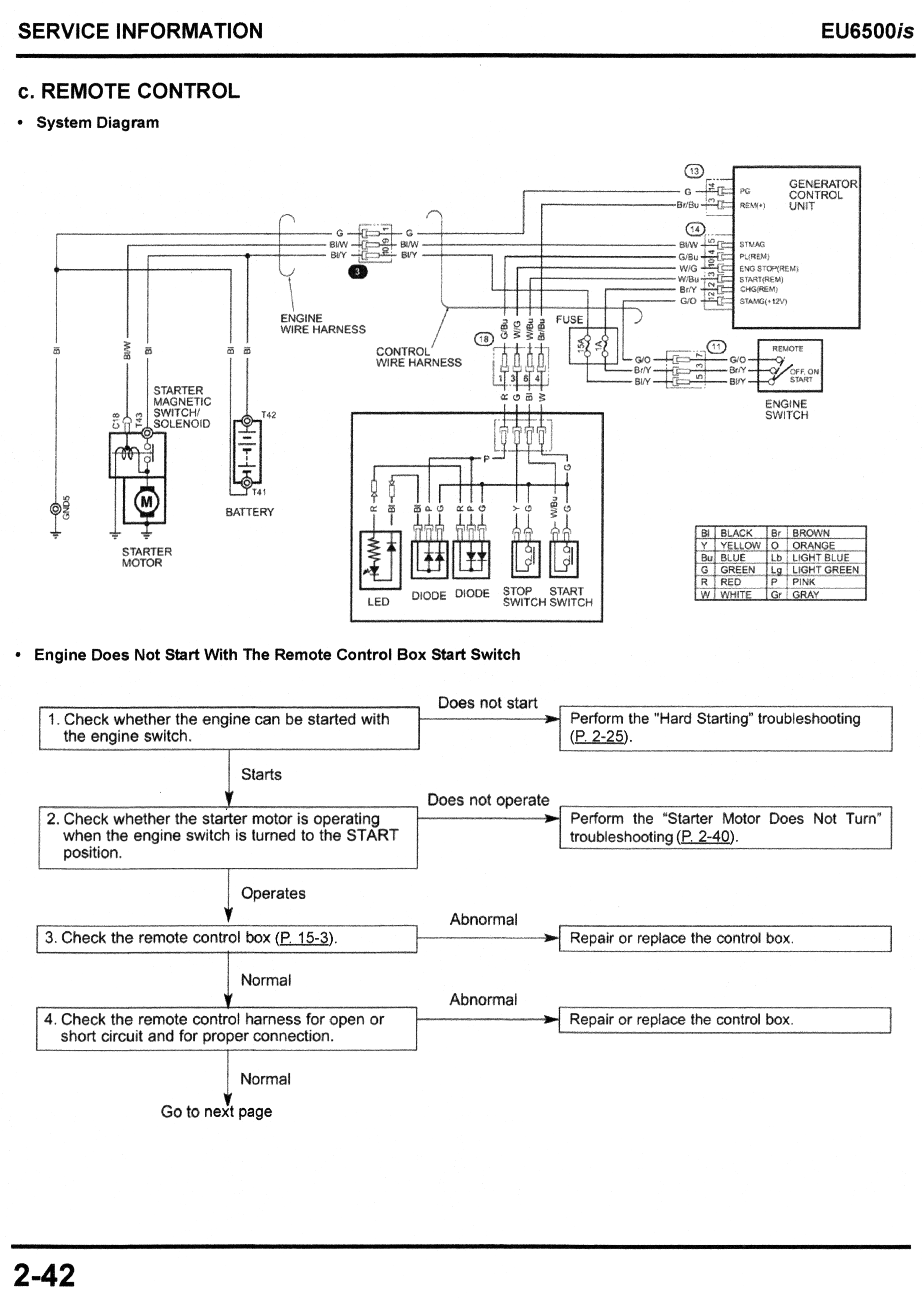
Below is a GIF of the factory remote control wiring diagram, from a heavily-chopped down full gen wiring diagram. It shows Pilot Lamp operation, but does not show pressing the START or STOP switches. In practice, a START request signal would have had to have occurred between slides 6 & 7, but the idea is to show how the PL works, not the START/STOP, since those are so simple and straightforward:
Given:
- Ign. Switch = REMOTE
- To START, connect 12v+, from remote connector pin 4, to pin 6.
- To STOP, connect 12v+, from remote connector pin 4, to pin 3.
- Honda EU6500is remote control wiring diagram (simplified)
- Remote_Wiring_Diagram_GIF_01.gif (436.25 KiB) Viewed 9898 times
[later]
There's a diagram similar to this in the Shop Manual, page 2-42, though it doesn't have my pretty lines, and doesn't explain how it works.