Unless you work with current-track diagrams for a living, or do PLC programming, I find that style difficult to translate into nuts-and-bolts.
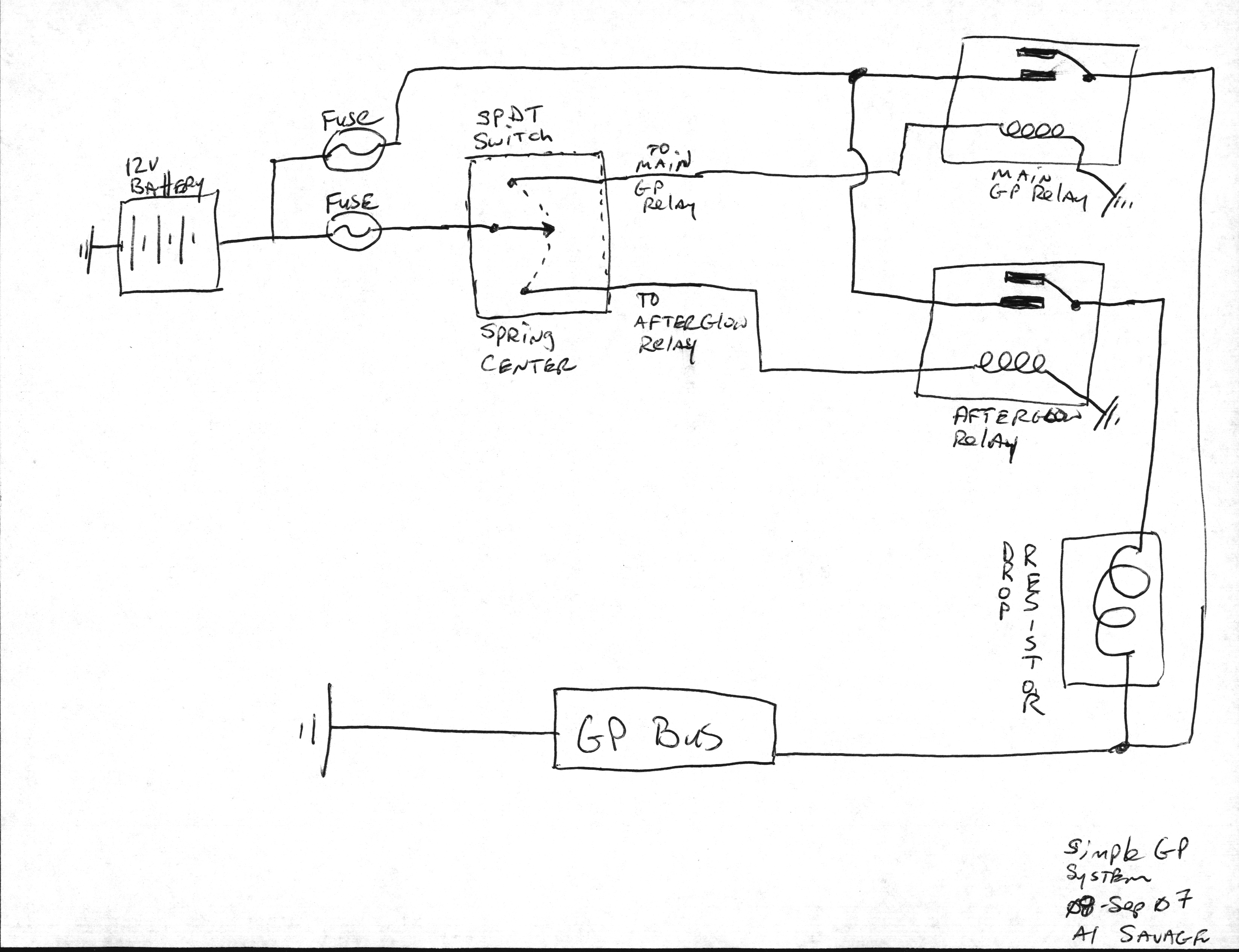
It took me longer to warm up my scanner (huge old Paragon 1200 A3: 4 minutes warmup, and it freezes the SCSI bus and thus the whole workstation while it waits for the lamp's color temperature to stablilze) than it did to create this:
Anybody can take that and wire it up. Translating your current track diagram requires both familiarity with the concept of current tracks, and logical-to-physical interpretation. Too easily screwed up.
Of course, my pen-and-paper diagram/schematic hybrid is non-editable and doesn't even use the correct IIEE symbols (and I resort to a "functional block" for the GP Bus because I do not want to bother to draw six GPs) -- but it is unambiguous and simple.
Last edited by asavage12 years ago, edited 1 time in total.
83 Maxima Sedan, LD28, 5 speed, white, 130k miles. My original Maxima.
83 Maxima Sedan converted from gasser, LD28, 5 speed, 2 tone blue, 230k miles 82 Maxima Sedan, LD28, 3 speed auto, 2 tone Gray/Silver, 140k miles
81 810 Sedan, LD28, 3 speed auto, rust, rust, and more rust!
I don't fault you for trying to help, but throwing out a ladder diagram to us, the great unwashed masses, isn't all that helpful. If I couldn't figure it out immediately -- and I have done this sort of thing to earn my daily bread in times past -- then it's safe to assume that 80%+ of your target audience will either end up with a dumb look on their pusses, or try to follow that and end up with something that smokes.
IOW: can you dumb it down a bit?
(Now I want to see a Basic Stamp controller in that ladder, OK?)
Considering I live in Tennessee and didn't finish high school, I don't hear that too often. I do work extensively in ladder diagrams and ladder logic, but it was always intuitive to me. I wasn't trying to talk over anyone's head. I don't draw much, and when I do, it is usually for my own consumption or an as built for an engineer to put into CAD. As for the basic stamp, I've never played with one. I do know of a fairly inexpensive 12 volt mini PLC...
Matt B.
83 Maxima Sedan, LD28, 5 speed, white, 130k miles. My original Maxima.
83 Maxima Sedan converted from gasser, LD28, 5 speed, 2 tone blue, 230k miles 82 Maxima Sedan, LD28, 3 speed auto, 2 tone Gray/Silver, 140k miles
81 810 Sedan, LD28, 3 speed auto, rust, rust, and more rust!
To be completley honest...Al's diagram is the easiest to understand. But thank you nonetheless Matt.
I am very intrigued by the idea that I am "afterglowing" the plugs at all times by having the relay wired through the dropping resistor.
I think I will take a few moments tomorrow and run a wire direct from the relay to the GP bus.
To play devil's advocate:
Why would you want or need a position for afterglow if the full +12 position is required to start the car most efficiently? I can't imagine it would be too likely for one to hold the switch down after they have started the car as the #2 relay is supposed to do.
[shrug]
Afterglow gives a better cold idle, less cold smoke, fewer cold emissions. Do I think anyone is going to hold down a batwing rocker after the engine's been started? No. But the OEM system does provide more heat after starting and during cranking (at a reduced rate) on the LD28 and later SD engines, and the SDs at least do need it. They are notorious for cold misfire.
I want automation in my GP system. If the OEM system worked, I'd stick with it, but it doesn't in a lot of cases, esp. warm starts. But if I'm going to go to the hassle of adding an Afterglow timer (which would be straightforward, since the actual timing is not critical), why not go all the way and provide a replacement for the OEM primary glow temp-compensated timer? That's the solution I want.
asavage wrote:Ben, I just want to get this clear: is your button toggling the main GP relay or the afterglow relay?
With those cycle times, I'm thinking afterglow. I use 15 secs. of afterglow to get mine fired up after a 17 mi. drive and 35 minutes cooling, otherwise it I have to crank a long time anyway.
I fixed this issue by connecting the relay straight to the bus bar. No more afterglow, no more sitting on the button for cold starts.
Warm start now takes ~5 secs. of glow time. Cold starting...we'll find out in a few minutes.
I had a hard time figuring out goglio704's ladder diagram, dumb look on my pusses... I guess we all just think a bit differently than him. But then again if your the kind of person that can engineer stuff for a CAD program... Ive played with CAD a bit and I know I have one that will work with the CNC, but I havent got that far yet. Im way more use to the other diagram system. Thanks for the try!
I had to put the glow system aside for now. I found out my fan and fan clutch from my gasser L would not work on my LD... So I had to modify a fan and fan clutch from a 92 VH45 to fit... to my dismay the original water pump was on the engine still and the shaft bearings showed a signicant amount of play as I turned the fan over... So I just realized that I threw away all my water pumps and my new ones are 150 miles away in storage. So I think I am forced now to go buy a $30 part that I know I have like 10 of somewhere. So while I have the front appart yet again... and Ive never built any diesel of any sort for real Im going to find someone to double check my injection pump timing and assembly to be sure.
Anyone else having problems with their harmonic balancers? Ive ran across quiet a few that had the elastomer bands come appart! I guess thats not to odd. The gas versions tend to come appart easily as well and the diesel has harder vibrations.
I pulled the engine today... got some pictures of the damage....
Doesnt look good.
Number 2 piston is shattered. Piston pieces fell out the hole you see. A lot of them in fact. Hopefully I will be able to procure a crank shaft... maybe I will steal one from a stroker engine... hehehehe and stick it in my diesel engien MUHAhahaha
homemade tach adapter using spare parts around the garage.
I dont have a bunch of technical details, like I said it was thrown together using random parts in my garage. A light bulb from the glove box of a 95 Q45, a 1985 Chevy HEI unit, and a random 4 pin Nissan Relay from a 95 Q45.
There are 2 wires coming off the EGR rev sensor. One of them can be used as a pickup the will go to the end marked pin 7 on my diagram and if memory serves me correctly the other should be power. I cant remember to be honest.
Its like 30USD in parts for anyone that wants to try it. Ive been working on the idea for a while and Im using this setup now with a gas motor and it works beautifully. The HEI unit cleans the voltage up and amplifies the signal. The relay emulates a ignition coil. And the tach works. Im using the stock early 3 wire Z gauge.